Rotating electrical machine

a technology of electrical machines and rotating parts, applied in the direction of mechanical energy handling, magnetic circuit rotating parts, magnetic circuit shape/form/construction, etc., can solve the problem of small influence of unbalanced attractive for

Inactive Publication Date: 2013-01-01
YASKAWA DENKI KK
View PDF14 Cites 8 Cited by
  • Summary
  • Abstract
  • Description
  • Claims
  • Application Information

AI Technical Summary

Problems solved by technology

Therefore, even when the capacity of the rotating electrical machine is increased, the influence of unbalanced attractive force is small.

Method used


Image

  • Rotating electrical machine
  • Rotating electrical machine
  • Rotating electrical machine

Examples


Embodiment Construction

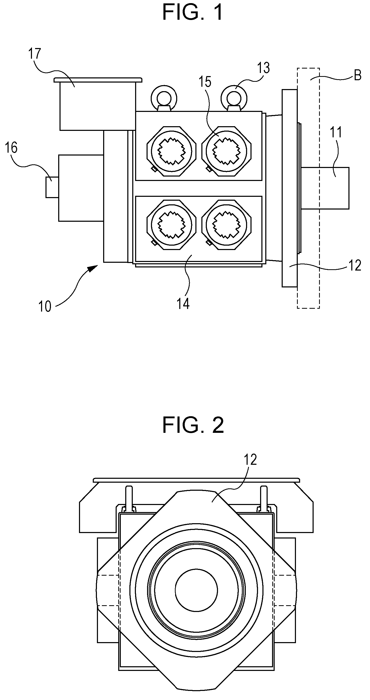
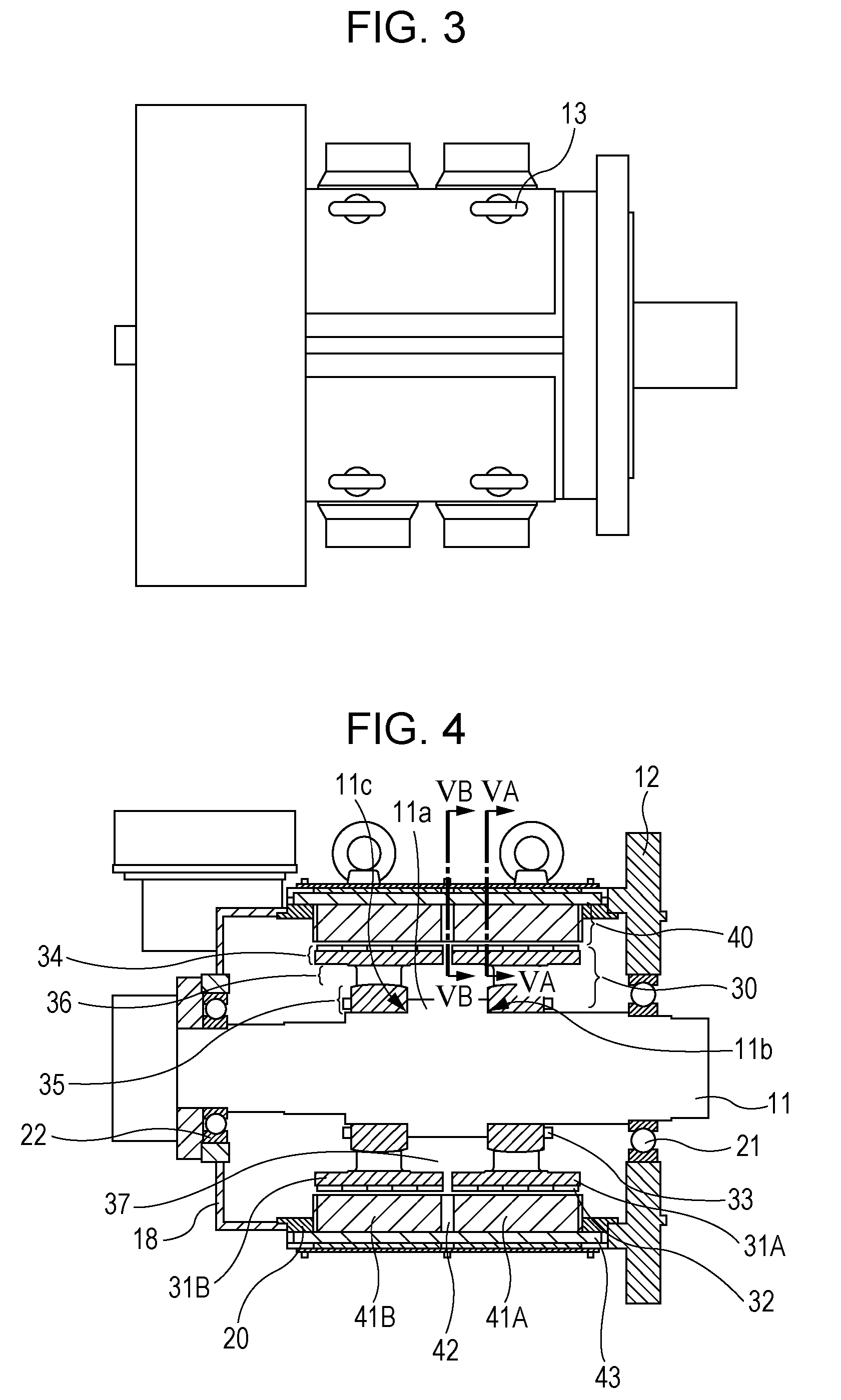
[0016]The external structure of a rotating electrical machine 10 according to an embodiment of the present invention will be described with reference to FIGS. 1 and 3. FIG. 1 is a side view of the rotating electrical machine 10, FIG. 2 is a front view of the rotating electrical machine 10, and FIG. 3 is a top view of the rotating electrical machine 10.

[0017]Referring to FIGS. 1 to 3, the rotating electrical machine 10 is a large motor having an extremely high output. The rotating electrical machine 10 is fixed with bolts (not shown) to a bracket B with a plate-shaped flange unit 12 provided therebetween. The rotating electrical machine 10 is fixed such that a shaft 11 extends horizontally. Four rings 13 for suspending the rotating electrical machine 10 with a crane are provided at the top of the rotating electrical machine 10. A surface of the rotating electrical machine 10 is covered by a cover 14, and four cooling fans 15 are provided at each side of the rotating electrical machin...


PUM


Abstract

A rotating electrical machine includes a flange provided at one end of a hollow frame in an axial direction; a rotor including a shaft, the shaft being rotatably supported by the flange; and a stator fixed to an inner section of the frame, the stator surrounding the rotor. The rotor includes a first rotor core and a second rotor core arranged in the axial direction and having recesses formed in the axial direction, and a rotor-core space defined by the recesses that are formed in the first rotor core and the second rotor core and that face each other.

Description

CROSS-REFERENCE TO RELATED APPLICATION[0001]The present application claims priority under 35 U.S.C. §119 to Japanese Patent Application No. 2010-059770, filed Mar. 16, 2010. The contents of the application are incorporated herein by reference in their entirety.BACKGROUND OF THE INVENTION[0002]1. Field of the Invention[0003]The present invention relates to rotating electrical machines.[0004]2. Discussion of the Background[0005]Japanese Unexamined Patent Application Publication No. 2002-281721 discloses a rotating electrical machine suitable for use as a large-capacity rotating electrical machine. The rotating electrical machine has a combination of the number of poles and the number of coils suitable for using the rotating electrical machine as a permanent magnet synchronous motor. Accordingly, an induced voltage waveform is close to a sine wave, and the amplitude of a cogging torque is reduced so that the required skew angle can be reduced. Therefore, even when the capacity of the r...

Claims


Application Information

Patent Timeline
Patent Type & Authority Patents(United States)
IPC IPC(8): H02K7/20H02K16/00H02K47/14H02K47/00H02K17/44
CPCH02K1/146H02K1/185H02K1/278H02K9/04H02K16/00H02K21/16
Inventor KAMIKI, YASUAKI
Owner YASKAWA DENKI KK
Why Eureka
Try Eureka