Complex-operation input device

a technology of input device and complex operation, which is applied in the direction of coding, pulse technique, instruments, etc., can solve the problems of inability to design, inability to detect the rotation of the dial knob, undetectable changes in the detection state of the rotation sensor, etc., and achieves the reduction of cost, easy to use, and the effect of compactness of the entire devi

Active Publication Date: 2013-01-08
ALPS ALPINE CO LTD
View PDF9 Cites 5 Cited by
  • Summary
  • Abstract
  • Description
  • Claims
  • Application Information

AI Technical Summary

Benefits of technology

[0015]According to this configuration, when sliding operation is performed, the sliding operation is detected before there is a change in the detection state of the rotation detecting portion. Therefore, rotation detection in that case can be determined to be caused by the sliding operation. Furthermore, in this configuration, a complicated design for an adjustment between clicking positions and sensor positions is not necessary. Consequently, in the complex-operation input device that allows for rotating operation and sliding operation, misdetection of rotating operation during sliding operation is prevented, and the design load is reduced.
[0017]With the complex-operation input device having such a configuration, the first detecting portion provided on the base can detect sliding-operation information (such as the sliding direction) and the second detecting portion provided on the same base can detect rotating-operation information (such as the rotational amount and the rotational direction). Therefore, with the first detecting portion and the second detecting portion disposed on the same surface of the base, the thickness of the entire device can be significantly reduced. Furthermore, since insert terminals and harnesses for outputting signals detected by the first detecting portion and the second detecting portion to an external circuit are not required, cost reduction can be readily achieved. Moreover, since the first detecting portion, the second detecting portion, the slider holder, and the holder-slider unit can all be disposed within a small space with about a size that can be covered by the rotor, compactness of the entire device can be facilitated. In addition, since the second detected portion can be provided on the outermost periphery of the rotor, high accuracy in rotation detection can be readily ensured.

Problems solved by technology

In the complex-operation input device described above, since the plane of rotation of the operable knob rotating in response to rotating operation is parallel to the sliding direction in which the operable knob slides in response to sliding operation, displacement of the operable knob due to the sliding operation can result in a change in the detection state of the rotation sensor that detects rotation of the operable knob, possibly resulting in misdetection.
The technology disclosed in Japanese Unexamined Patent Application Publication No. 2008-16298 is configured to cancel a rotating-operation signal if the dial knob is slidably operated, but does not take into account the fact that the detection state of the rotation sensor undesirably changes prior to detection of the sliding operation.
Therefore, when the dial knob is slidably operated, the rotation detecting mechanism stops electrically functioning, thus causing, for example, the detection state of the rotation sensor previously in an “ON” state to become an “OFF” state and possibly resulting in detection that the dial knob has been rotated.
However, this configuration has limitations in terms of design and leads to an increase in design load.
Therefore, the fixed base requires a reasonable thickness, disadvantageously leading to a hindrance to thickness reduction of the device.
In addition, since insert terminals and harnesses for outputting the signals detected by the slide sensor and the rotation sensor to an external circuit are required, the cost of components and the cost of assembly can easily increase.
Furthermore, in this configuration, a complicated design for an adjustment between clicking positions and sensor positions is not necessary.

Method used


Image

  • Complex-operation input device
  • Complex-operation input device
  • Complex-operation input device

Examples


Embodiment Construction

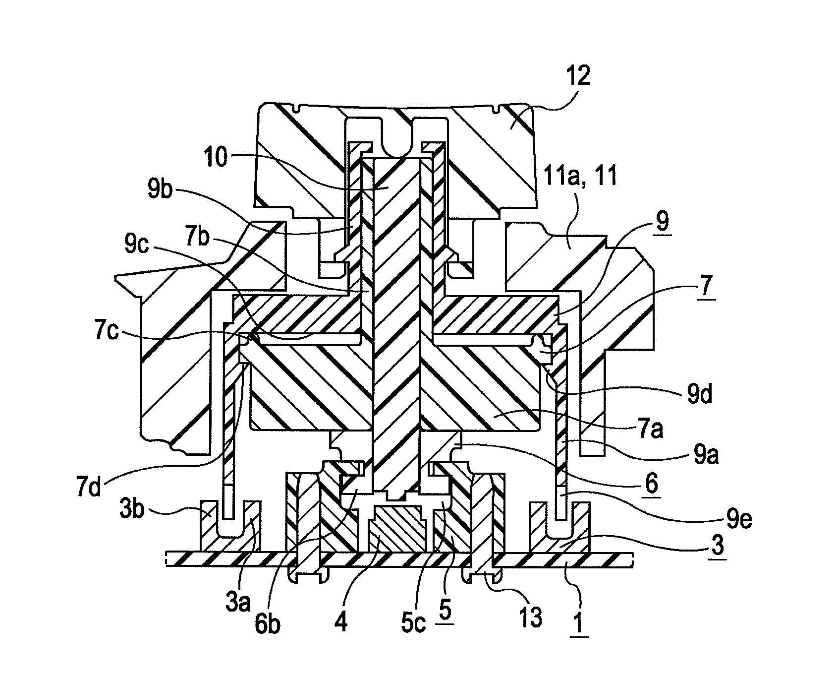
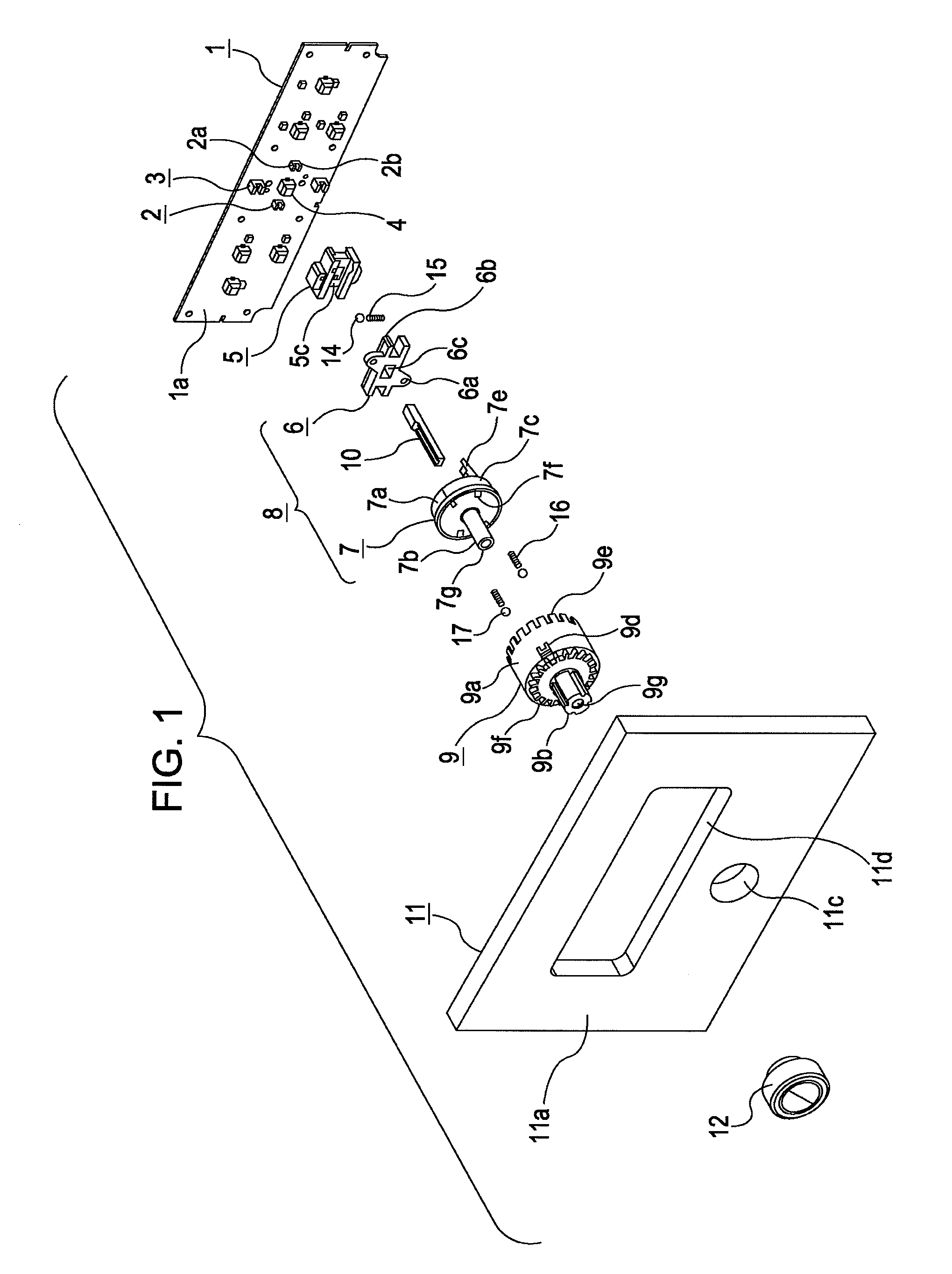
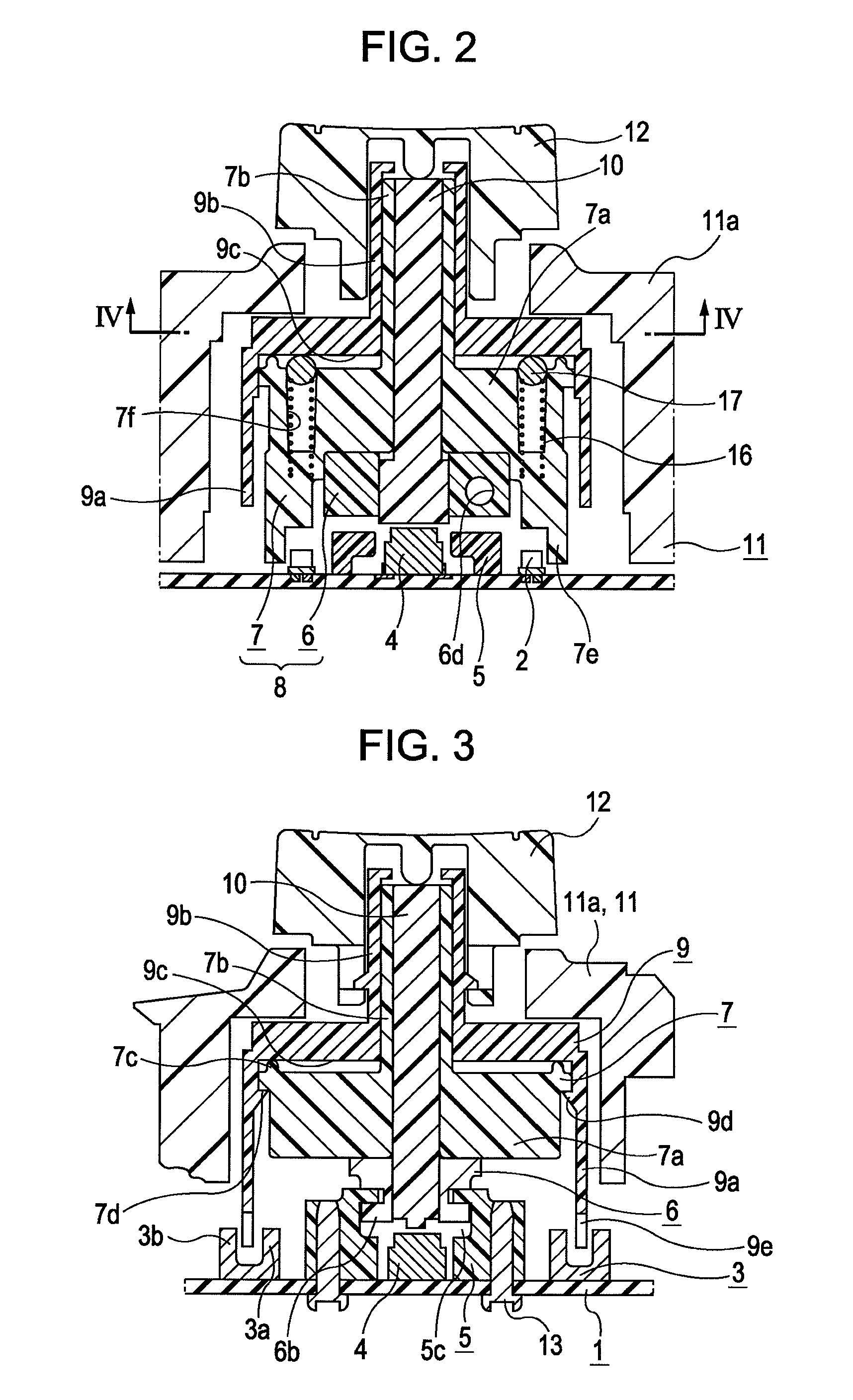
[0030]A complex-operation input device according to an embodiment of the present invention will be described below with reference to the drawings. First, the mechanical configuration of the complex-operation input device according to this embodiment will be described with reference to FIGS. 1 to 7. This input device is installed near a driver seat of a vehicle and is used for operating various functions of a vehicle air conditioner. As shown in an exploded perspective view in FIG. 1, the input device mainly includes a substrate (base) 1 on which slide sensors 2, rotation sensors 3, a push switch 4, and the like are disposed, a slider holder 5 fixed on the substrate 1, a holder-slider unit 8 formed by screwing a slider 6 slidably supported by the slider holder 5 onto a rotor holder 7, a rotor 9 rotatably supported by the rotor holder 7, an actuator 10 for pressing and driving the push switch 4, a casing 11 that accommodates these components 1 to 10, and an operable knob 12 spline-fit...


PUM


Abstract

A complex-operation input device having an operable knob held in a rotatable and slidable manner includes a rotation sensor that detects rotation of the operable knob on the basis of displacement of a second detected portion, and a slide sensor that detects sliding of the operable knob on the basis of displacement of a first detected portion. The direction in which the second detected portion moves with the sliding of the operable knob is substantially orthogonal to a rotation axis about which the operable knob rotates. The slide sensor is disposed such that, when the operable knob is slid, the slide sensor detects the sliding before the rotation sensor detects the displacement of the second detected portion.

Description

CLAIM OF PRIORITY[0001]This application claims benefit of the Japanese Patent Application No. 2009-147766 filed on Jun. 22, 2009 and Japanese Patent Application No. 2009-157891 filed on Jul. 2, 2009, which are hereby incorporated by reference in their entirety.BACKGROUND OF THE DISCLOSURE[0002]1. Field of the Disclosure[0003]The present disclosure relates to complex-operation input devices that at least allows for rotating operation and sliding operation.[0004]2. Description of the Related Art[0005]In the related art, a known example of a complex-operation input device of this type has a configuration in which a shaft member is slidably supported by a slide recess in a fixed base, a slide sensor is mounted at the inner bottom of this slide recess. A rotation sensor is mounted on a substrate placed and fixed on the fixed base, and an operable knob is rotatably attached to the shaft member protruding upward from the slide recess in the fixed base (for example, see US Patent No. 2009 / 0...

Claims


Application Information

Patent Timeline
Patent Type & Authority Patents(United States)
IPC IPC(8): H03K17/94
CPCH01H25/008H03K17/965H03K17/968H01H2025/004H01H2239/022H03K2217/94063
Inventor KATO, KIYOAKIUENOMACHI, TAKASHIEBINUMA, SHINGO
Owner ALPS ALPINE CO LTD
Why Eureka
Try Eureka