Double-layer horizontal sedimentation tank for drinking water purification of surface water

An advection and surface water technology, applied in the direction of settlement tanks, etc., can solve the problems of poor mud discharge, large floor area, large floor area of ​​advection sedimentation tanks, etc., and achieves easy construction, small floor space, and structural simple effect

Inactive Publication Date: 2015-07-22
SHIHEZI UNIVERSITY
View PDF4 Cites 3 Cited by
  • Summary
  • Abstract
  • Description
  • Claims
  • Application Information

AI Technical Summary

Problems solved by technology

[0003] The purpose of the present invention is to provide a double-layer advection sedimentation tank for surface water drinking water purification, which overcomes the problem of poor mud discharge caused by hydrostatic pressure mud discharge in the existing advection sedimentation tank, and solves the problem that the advection sedimentation tank occupies a large area, etc. The problem is that the double-layer sedimentation tank can use the hydrostatic pressure of the upper and lower sedimentation areas to achieve smooth mud discharge in the lower sedimentation area, and the upper sedimentation area can improve the working efficiency of the sedimentation tank by adding mud scraping trucks, thus effectively overcoming the conventional advection sedimentation. Problems with large pool footprints

Method used


Image

  • Double-layer horizontal sedimentation tank for drinking water purification of surface water
  • Double-layer horizontal sedimentation tank for drinking water purification of surface water
  • Double-layer horizontal sedimentation tank for drinking water purification of surface water

Examples


Embodiment Construction

[0018] The present invention will be described in detail below in conjunction with the accompanying drawings and specific embodiments.

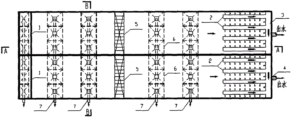
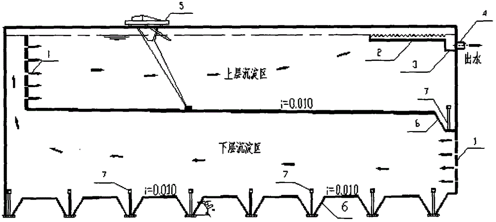
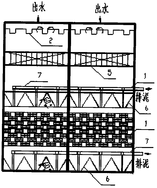
[0019] A structure of surface water drinking water purification double-deck advection sedimentation tank, such as Figure 1-3 As shown, it consists of the lower water intake area, the lower sedimentation area, the upper water intake area, the upper sedimentation area, the water outlet area, the lower mud discharge area and the upper mud discharge area.

[0020] Both the upper water intake area and the lower water intake area use the perforated flower wall 1 for water distribution, which plays the role of uniform water replenishment and energy dissipation. The water inlet perforated flower wall 1 is built with bricks or concrete blocks, and the part outside the holes is plastered with cement mortar; the upper and lower water inlet holes of the flower wall are staggered, and at the same time, the wall from 0.3 to 0.5m above the sedimentation su...


PUM


Abstract

The invention discloses a double-layer horizontal sedimentation tank for drinking water purification of surface water. The double-layer horizontal sedimentation tank comprises an upper layer tank body and a lower layer tank body; a water inlet perforated wall is arranged at the position of a water inlet on the right of the lower layer tank body; the lower layer tank body is communicated with the upper layer tank body through a water inlet perforated wall arranged on the inner left side of the upper layer tank body; a plurality of rows of sludge hoppers are arranged in the lower layer tank body; sludge discharge pipes are arranged at the bottoms among each row of the sludge hoppers, and the upper ends of the sludge discharge pipes are communicated with a sludge discharge main pipe; the tank bottom slope of a sludge discharge area in the upper layer tank body is equal to or larger than 0.01; a single row of sludge hoppers are arranged at the slope bottom on the right side of the sludge discharge area in the upper layer tank body; a sludge scrapping traveler is arranged on the upper layer tank body, and used for scrapping sludge from the bottom of the upper layer tank body; finger-type effluent weirs are arranged on the upper right part of the upper layer tank body; a water collection main pipe is arranged at the tail ends of the finger-type effluent weirs. Through the adoption of the double-layer horizontal sedimentation tank, the problems of unsmooth sludge discharge due to a hydrostatic pressure manner adopted by the conventional horizontal sedimentation tank, a relatively large occupied area of the conventional horizontal sedimentation tank and the like are solved.

Description

technical field [0001] The invention belongs to the technical field of water supply and drainage engineering, and relates to a double-layer advection sedimentation tank for surface water drinking water purification, which is suitable for a sedimentation tank for drinking water purification of high-turbidity surface water sources, and also for a primary sedimentation tank in a sewage treatment system. Background technique [0002] The sedimentation tank is an indispensable structure in the whole purification system in the drinking water purification project of high turbidity surface water. At present, the types of sedimentation tanks used in the surface water drinking water project are advection type, radial flow type and vertical flow type. Among them, the advection sedimentation tank is the earliest and most widely used mud-water separation structure in waterworks in my country due to its simple structure, good sedimentation effect, stable performance, and strong adaptabilit...

Claims


Application Information

Patent Timeline
Patent Type & Authority Applications(China)
IPC IPC(8): B01D21/02
Inventor 刘生宝王健康孙志华徐凤杨广刘芬江煜王春霞陈真于若鹏郝燕
Owner SHIHEZI UNIVERSITY
Why Eureka
Try Eureka