Dynamic classification and grouping of network traffic for service application across multiple nodes

a network traffic and service application technology, applied in the field of dynamic classification and grouping of network traffic for service application across multiple nodes, can solve the problems of network operator compromising its desired classification schema, not matching the view of network operator, and incurring an operation, administration and management (oa&m) cos

Active Publication Date: 2013-01-08
RIBBON COMM OPERATING CO INC
View PDF26 Cites 126 Cited by
  • Summary
  • Abstract
  • Description
  • Claims
  • Application Information

AI Technical Summary

Problems solved by technology

For example, network operators may be required to pre-configure (static) data to define these groups and allocate subscribers to these groups, thus incurring an Operations, Administration, and Management (OA&M) cost to set up a subscriber and again each time a service or subscriber changes.
In addition, classifications / grouping constructs within a network node's data model typically have a fixed meaning (as determined by the equipment vendor's software), and may not match the network operator's view of how it classifies subscribers or defines services.
As a result, equipment vendors either develop custom software for network operators, or the network operator compromises its desired classification schema (in terms of costs, efficiencies, or quality of service delivered).
Also, classification / grouping data models are frequently flat or hierarchical, which can make it difficult to have subscribers belong to multiple classifications simultaneously.
Thus, a network operator may have difficulty defining a consistent classification and service view for a given subscriber or service across all the equipment through which the subscriber's service is delivered.
Another difficulty with traffic classification arises when more than one network node (such as a border / edge device and a centralized session device) each have different information about the traffic flow available based on the specific scope of signaling or configuration to which the network nodes are exposed.
However, this approach can require frequent incremental changes to each node involved such that services can be slow and / or costly to introduce to a network.
This approach can also result in traffic flow classification and service application decisions based on incomplete information, simply because that is what is available, which leads to inefficiencies, inaccuracies or undesirable user experiences.

Method used


Image

  • Dynamic classification and grouping of network traffic for service application across multiple nodes
  • Dynamic classification and grouping of network traffic for service application across multiple nodes
  • Dynamic classification and grouping of network traffic for service application across multiple nodes

Examples


example use case 1

[0114

[0115]FIG. 7 is a block diagram of an exemplary system 700 for dynamic classification and grouping of network traffic for service application across multiple nodes. In the following example, a service provider or other operator of a network wishes to record calls originating at a specific access network segment. In this example, UE A 701 or UE B 702 belongs to the access network segment 705 that the operator wishes to record. Therefore, traffic flows originating from UE A 701 or UE B 702 match the entry criteria to belong to a “RECORD_CALL” classification group 711 defined at the first network server 710 (e.g., a session border controller). The classification group 711 is configured to include the “RECORD_CALL” tag 712 in the internodal signaling from the first network server 710 to the second network server 720 (e.g., an application server). Traffic flows that originate from UE A 701 or UE B 702 have the “RECORD_CALL” tag 712 added as the traffic flow progresses to the second ...

example use case 2

[0118

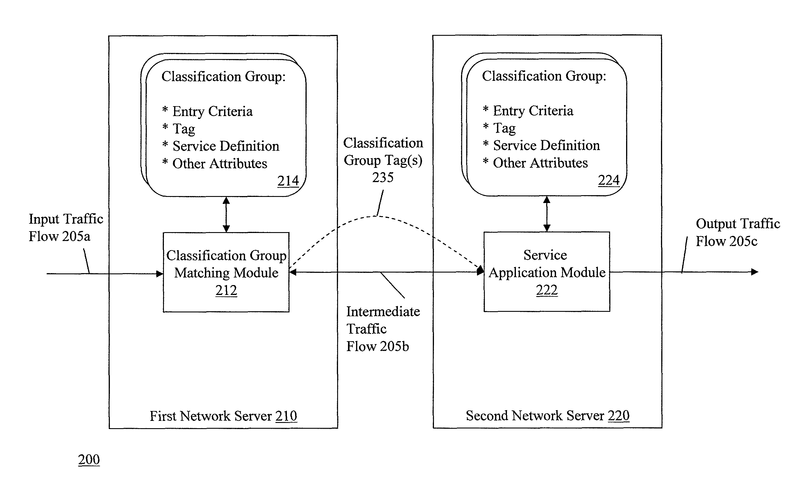
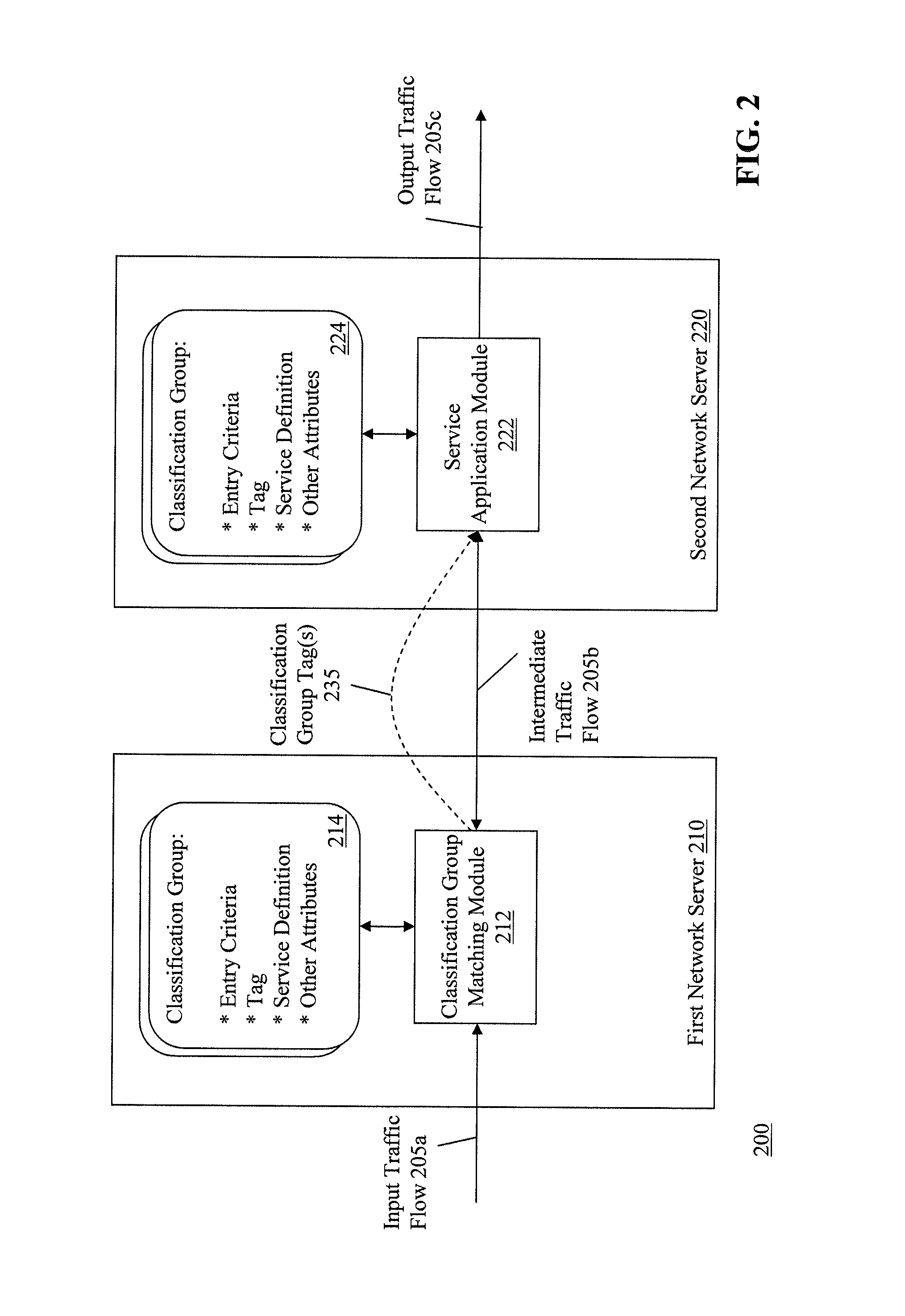
[0119]Referring back to FIG. 2, in this use case, the first network server 210 and the second network server 220 have classification group “X” (e.g., 214 and 224) defined at each server, respectively. The first network server 310 matches a traffic flow (e.g., 205), assigns membership to classification group “X” (e.g., 214), and applies a tag 235 associated with group “X”214 to the traffic flow. The second network server 220 receives the traffic flow and compares the attributes of the traffic flow against the entry criteria of classification group “X”224 located at the second server 220. In some embodiments, classification group “X”224 on the second network server 220 can also have independent criteria, depending on how the operator configures the groups. For example:[0120]a. Receiving Tag X 235 from the first network server 210 can override the entry criteria associated with classification group X 224 and the traffic flow is automatically assigned to the group 224. In this exam...

example use case 3

[0122

[0123]Continuing with FIG. 2, in this use case, the first network server 210 has defined classification group X 214, but the second network server 220 has not defined classification group. In this example, the second network server 220 ignores the tag 235 applied to the traffic flow 205 at the first network server 210, and the second network server 220 applies default service logic to the traffic flow.


PUM


Abstract

Methods and apparatuses, including computer program products, are described for applying service based on classification and grouping of traffic flows. The method includes receiving a traffic flow, and matching the traffic flow to classification groups. The matching includes determining a first event associated with the traffic flow, comparing attributes of the first event with entry criteria of the classification groups, and assigning the first event to one or more classification groups where the first event meets the entry criteria of the one or more classification groups. The method includes identifying one or more service definitions for the traffic flow based on the classification groups assigned to the traffic flow, reconciling the one or more service definitions for the traffic flow, and providing a service to the traffic flow based on the reconciled service definitions.

Description

FIELD OF THE INVENTION[0001]The subject matter of this application relates generally to methods and apparatuses, including computer program products, for dynamic classification and grouping of network traffic for service application across multiple nodes.BACKGROUND OF THE INVENTION[0002]In the field of telecommunications, it is common for different classes of network traffic to exist. Network traffic is classified by a variety of means. A common example is traffic belonging to a particular subscriber to the network. Subscribers are grouped into different classifications for a variety of reasons, including, but not limited to, the level of service purchased (minutes, bandwidth, features etc), their location / geography, the type of handset / user equipment (UE) utilized, the business or enterprise to which they belong, or the network segment / server or point-of-interconnect to which they are assigned / attached.[0003]Different nodes in the network may have lesser or greater (or even complet...

Claims


Application Information

Patent Timeline
Patent Type & Authority Patents(United States)
IPC IPC(8): G06F15/16
CPCH04L12/66
Inventor HART, JUSTIN SCOTT
Owner RIBBON COMM OPERATING CO INC
Why Eureka
Try Eureka