Radio frequency tank eigenmode sensor for propellant quantity gauging

a radio frequency tank and propellant quantity technology, which is applied in the direction of liquid/fluent solid measurement, machines/engines, instruments, etc., can solve the problems of uncertainty in the configuration of the liquid in the tank at low or partial gravity, the complexity of converting the radio frequency spectrum of the tank into a propellant quantity reading, and the uncertainty of the configuration of the liquid which is sloshing or splashing within the tank at any gravity

Inactive Publication Date: 2013-01-15
NASA THE UNITED STATES GOVERNMENT AS REPRESENTED BY THE ADMINISTATOR OF
View PDF29 Cites 15 Cited by
  • Summary
  • Abstract
  • Description
  • Claims
  • Application Information

AI Technical Summary

Benefits of technology

[0010]One advantage of this invention is that the liquid in the tank does not have to be settled first before taking a ...

Problems solved by technology

While known measurement methods perform well for their intended purpose, there are limitations.
One limitation is that the configuration of the liquid in the tank at low or partial gravity is uncertain.
Another limitation is that the configuration of a liquid, whi...

Method used


Image

  • Radio frequency tank eigenmode sensor for propellant quantity gauging
  • Radio frequency tank eigenmode sensor for propellant quantity gauging
  • Radio frequency tank eigenmode sensor for propellant quantity gauging

Examples


Embodiment Construction

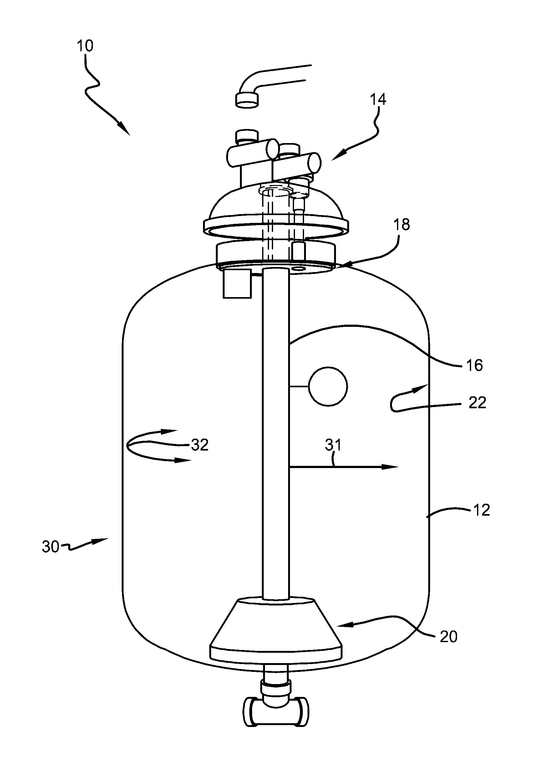
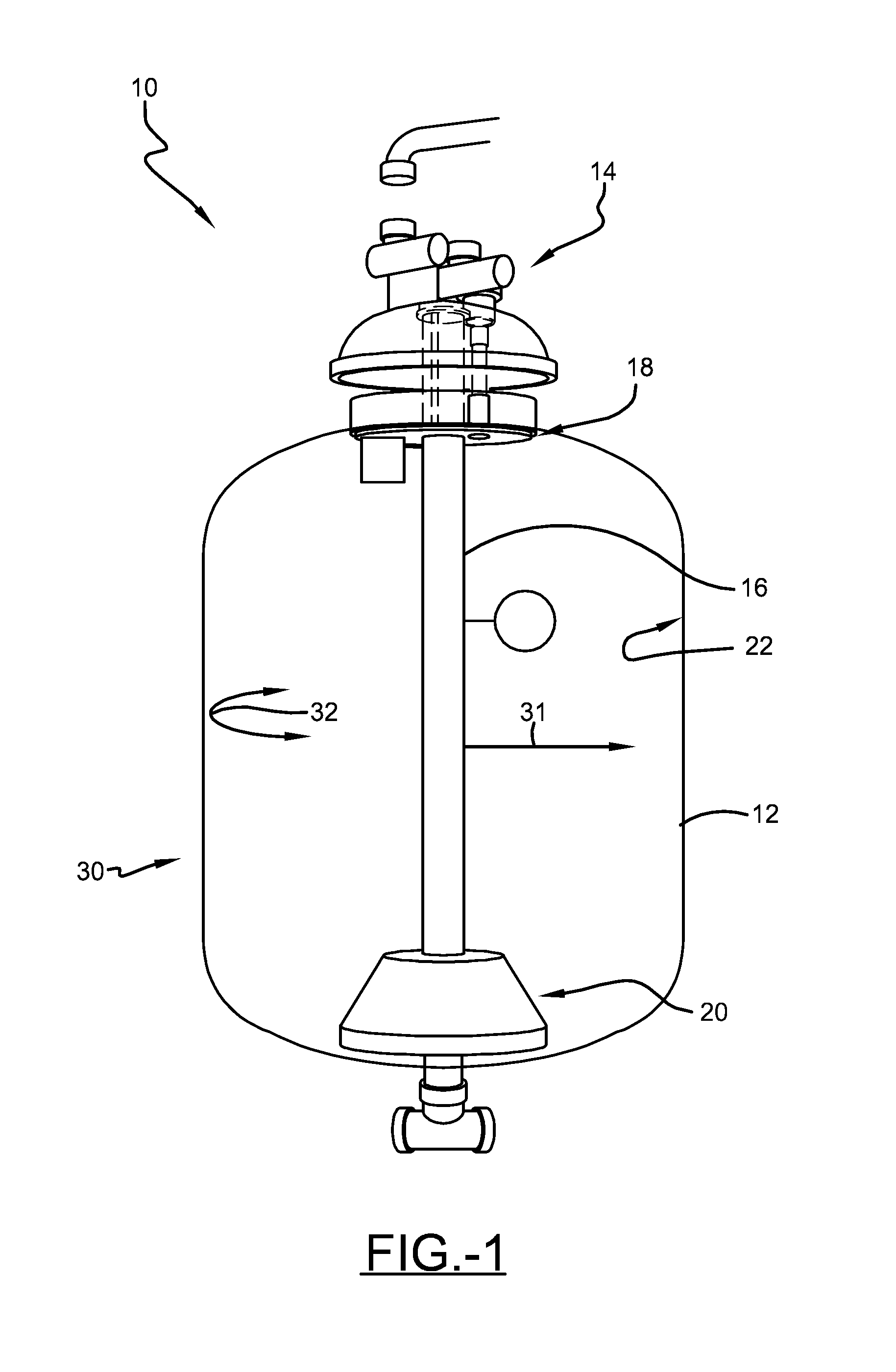
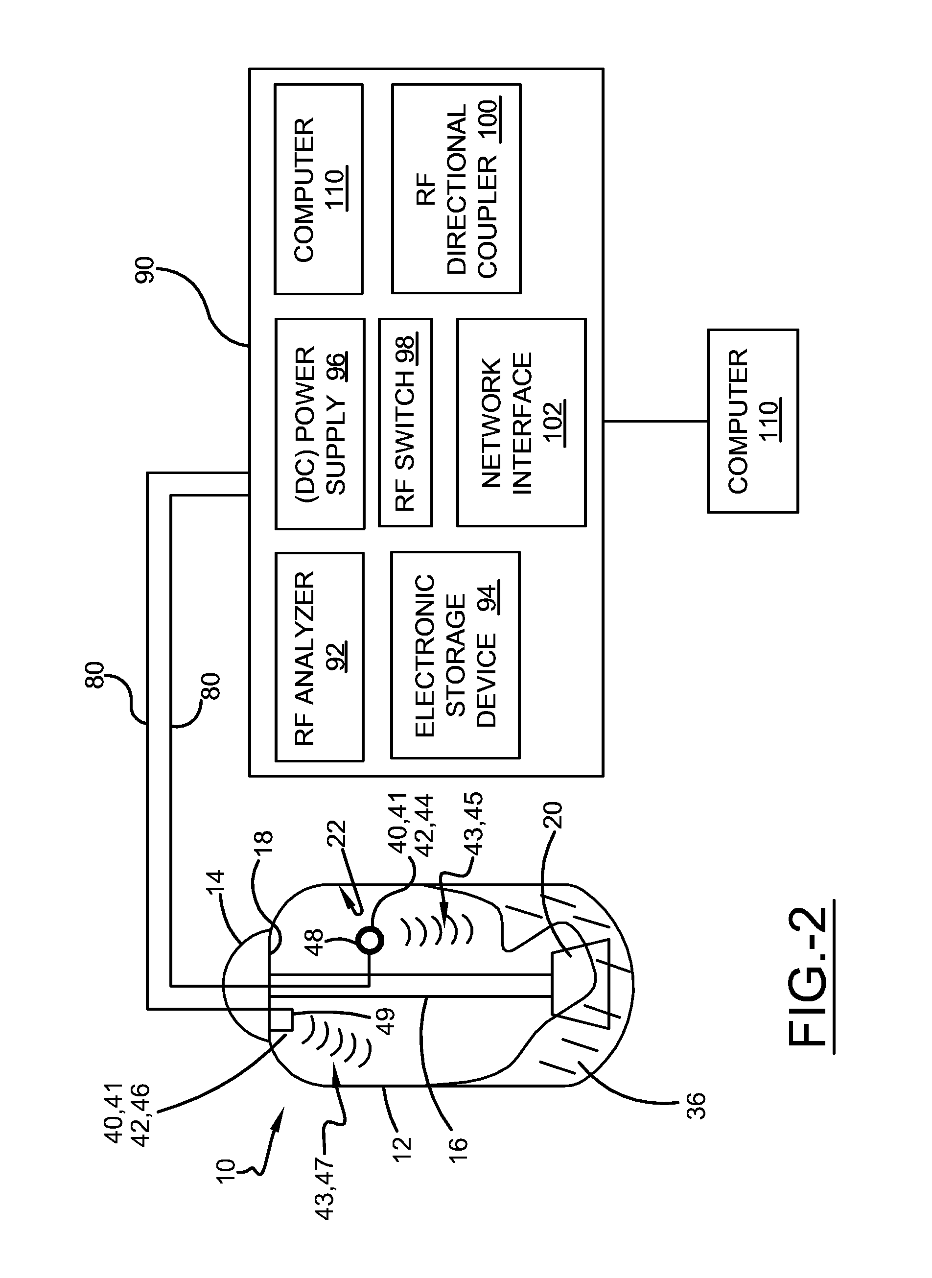
[0027]Referring to the drawings wherein the showings are for purposes of illustrating embodiments of the invention only and not for purposes of limiting the same, and wherein like reference numerals are understood to refer to like components, FIGS. 1 and 2 show a propellant tank 10 according to one embodiment of this invention. The tank 10 may have any design or shape chosen with ordinary skill in the art. The tank 10 may be located in many various gravity environments including, but not limited to, the Earth's gravity (about 1 g), low gravity (less than or equal to about 0.5 g), the Moon's gravity, or zero gravity. The tank 10 may include walls 12, a lid 14, a central tube 16, a baffle plate 18, a sump 20, and other tank hardware as is well known in the art. The walls 12 may be formed of metal, and in one embodiment, are formed of stainless steel. Alternatively, the walls 12 may be formed of any non-metallic or partially metallic material chosen by one with ordinary skill in the ar...


PUM


Abstract

A method for measuring the quantity of fluid in a tank may include the steps of selecting a match between a measured set of electromagnetic eigenfrequencies and a simulated plurality of sets of electromagnetic eigenfrequencies using a matching algorithm, wherein the match is one simulated set of electromagnetic eigenfrequencies from the simulated plurality of sets of electromagnetic eigenfrequencies, and determining the fill level of the tank based upon the match.

Description

I. ORIGIN OF THE INVENTION[0001]The invention described herein was made by an employee of the United States Government and may be manufactured and used by or for the Government for Government purposes without the payment of any royalties thereon or therefore.II. BACKGROUND OF THE INVENTION[0002]A. Field of Invention[0003]This invention relates generally to measuring the quantity of liquid in a storage container and more particularly to gauge the quantity of propellant in a tank.[0004]B. Description of the Related Art[0005]It is well known in the art to measure the amount of liquid in a storage tank. The general concept of measuring the electromagnetic eigenmodes of a tank as a method to gauge the quantity of liquid in a propellant tank dates back to 1966, when Lockheed Missiles and Space Company first tested the technique as a level sensor in tanks partially filled with RP-1, liquid hydrogen, and liquid oxygen.[0006]While known measurement methods perform well for their intended pur...

Claims


Application Information

Patent Timeline
IPC IPC(8): G01F22/00
CPCG01F22/00G01F23/284
Inventor ZIMMERLI, GREGORY A.
Owner NASA THE UNITED STATES GOVERNMENT AS REPRESENTED BY THE ADMINISTATOR OF
Why Eureka
Try Eureka