
Drive control circuit for linear vibration motor

a technology of linear vibration and control circuit, which is applied in the direction of motor/generator/converter stopper, dynamo-electric converter control, instruments, etc., can solve the problems of vibration weakening and yield drop

Active Publication Date: 2011-07-28
SEMICON COMPONENTS IND LLC
View PDF6 Cites 3 Cited by
  • Summary
  • Abstract
  • Description
  • Claims
  • Application Information

AI Technical Summary

Benefits of technology

[0009]To address the foregoing problems, the inventor of the present invention had found out a method in which the eigen frequency of the linear vibration motor is estimated from zero crosses of an induced voltage occurring in a coil of an electromagnet and thereby the cycle width of a drive signal is adaptively controlled in such a manner that the frequency of the drive signal can agree with the eigen frequency thereof.

Problems solved by technology

Thus, in the conventional method where a fixed drive frequency is set to all drive circuits for the linear vibration motors, there are drive circuits with a significant disagreement between the eigen frequency of the motor and the drive frequency thereof, thereby causing a drop in the yield.
Also, even though the eigen frequency of the motor and the drive frequency thereof agree at first, there are cases where they deviate from each other with time and the vibration gets weaker.

Method used


Image

  • Drive control circuit for linear vibration motor
  • Drive control circuit for linear vibration motor
  • Drive control circuit for linear vibration motor

Examples


Embodiment Construction

[0052]The invention will now be described by reference to the preferred embodiments. This does not intend to limit the scope of the present invention, but to exemplify the invention.

[0053](Basic Configuration)

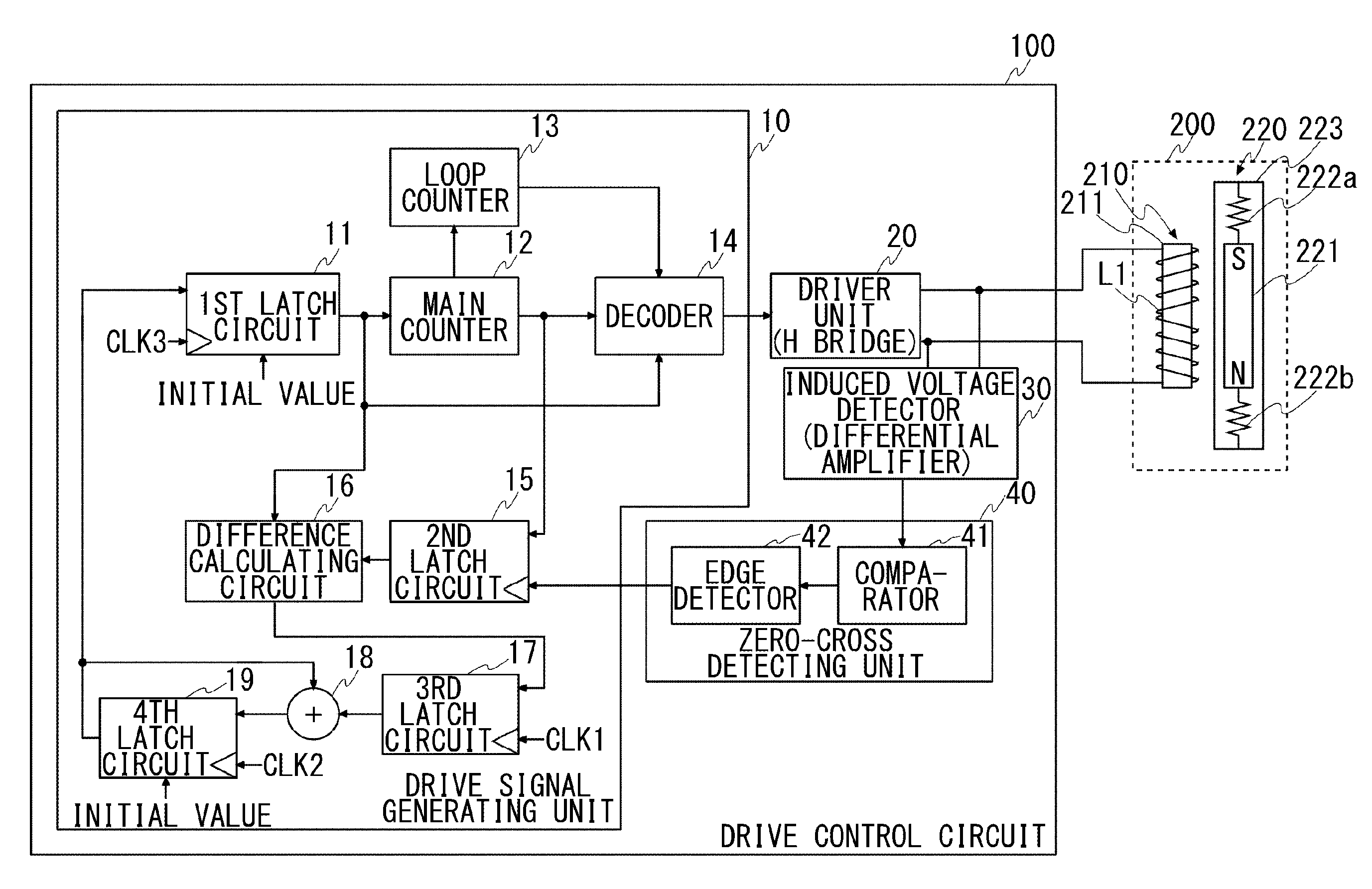
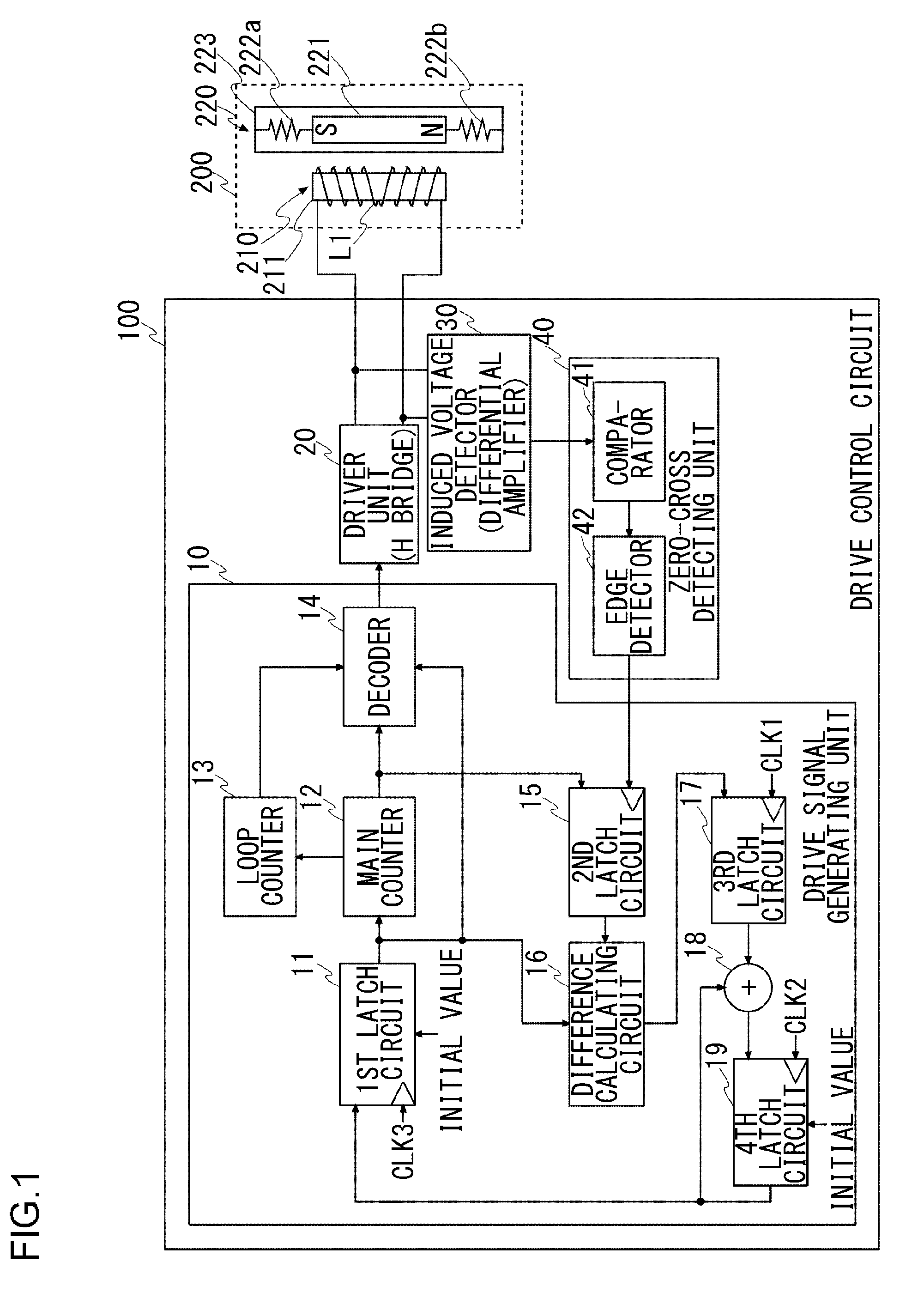
[0054]FIG. 1 shows a configuration of a drive control circuit 100 of a linear vibration motor 200 according to an embodiment of the present invention. The linear vibration motor 200 has a stator 210 and a vibrator 220, and at least one of the stator 210 and the vibrator 220 is constructed of an electromagnet. In the present embodiment, the stator 210 is constructed of an electromagnet. The stator 210 is formed such that a coil L1 is wound around a core 211 formed of a magnetic material; the stator 210 operates, as a magnet, with the current supplied to the coil L1. The vibrator 220 includes a permanent magnet 221, and the both ends (south pole side and north pole side) of the permanent magnet 221 are fixed to a frame 223 through springs 222a and 222b, respectively. The stator 2...


PUM


Abstract

A drive signal generating unit generates a drive signal used to alternately deliver a positive current and a negative current to a coil with a nonconducting period inserted between conducting periods. A driver unit generates a drive current in response to the drive signal generated by the drive signal generating unit and supplies the drive current to a coil. The drive signal generating unit estimates the eigen frequency of a linear vibration motor based on a detected position of the zero cross occurring in the coil during the nonconduting period, and the frequency of the drive signal is brought close to the estimated eigen frequency. The zero-cross detecting unit sets a detection window for avoiding the detection of zero cross of voltages other than the induced voltage. The zero-cross detecting unit enables a zero cross detected within the detection window and disables a zero cross detected outside the detection window.

Description

[0001]This application is based upon and claims the benefit of priority from the prior Japanese Patent Application No. 2010-017394, filed on Jan. 28, 2010, the entire contents of which are incorporated herein by reference.BACKGROUND OF THE INVENTION[0002]1. Field of the Invention[0003]The present invention relates to a drive control circuit used to control the drive of a linear vibration motor, including a vibrator and a stator, where the vibrator linearly oscillates back and forth relative to the stator.[0004]2. Description of the Related Art[0005]Though a linear vibration motor is used for a specific purpose of moving an electric shaver and the like, its use is expanding in recent years. For example, the linear vibration motor is used for an element that creates a vibration with which an operation feeling of a touch panel pressed down is to be fed back to a user. As haptics (sense of touch) engineering is finding rapidly increasing use, it is expected that the total number of line...

Claims


Application Information

Patent Timeline
IPC IPC(8): H02K33/00H02P25/06
CPCH02P25/028H02P25/034G01R19/175
Inventor MURATA, TSUTOMU
Owner SEMICON COMPONENTS IND LLC
Learn More