
Liquid level detecting device and sample applying system

a liquid level detection and liquid level technology, applied in the field of methods and apparatus of sample application systems, can solve the problems of lowering detection sensitivity, inability to obtain rapid results, and inability to detect liquid levels correctly, and achieve the effect of high sensitivity and reliability

Active Publication Date: 2013-01-22
SHENZHEN MINDRAY BIO MEDICAL ELECTRONICS CO LTD
View PDF16 Cites 3 Cited by
  • Summary
  • Abstract
  • Description
  • Claims
  • Application Information

AI Technical Summary

Benefits of technology

The patent is about a device that can detect liquid levels accurately and reliably in different environments. It has a high sensitivity for detecting small amounts of liquid.

Problems solved by technology

For example, when the sampling needle enters an environment such as a metal container, the capacitance change of the sampling needle itself is relatively apparent and thus tends to lead to incorrect detection of the liquid level.
Whereas in the case of a plastic container or when the container contains relatively little amount of liquid, the capacitance change of the sampling needle is relatively weak or insignificant in comparison to the change in capacitance due to the contact with the liquid surface and thus may result in a lowered sensitivity in detection.
This lowered sensitivity in detection of the liquid level often leads to a scenario that no result may be obtained quickly even when the sampling needle has indeed contacted the liquid level.
However, it is difficult for conventional liquid level detecting devices to meet such requirements because these conventional liquid level detection devices tend to cause errors in test results when it is needed to perform detection under various complex environments.

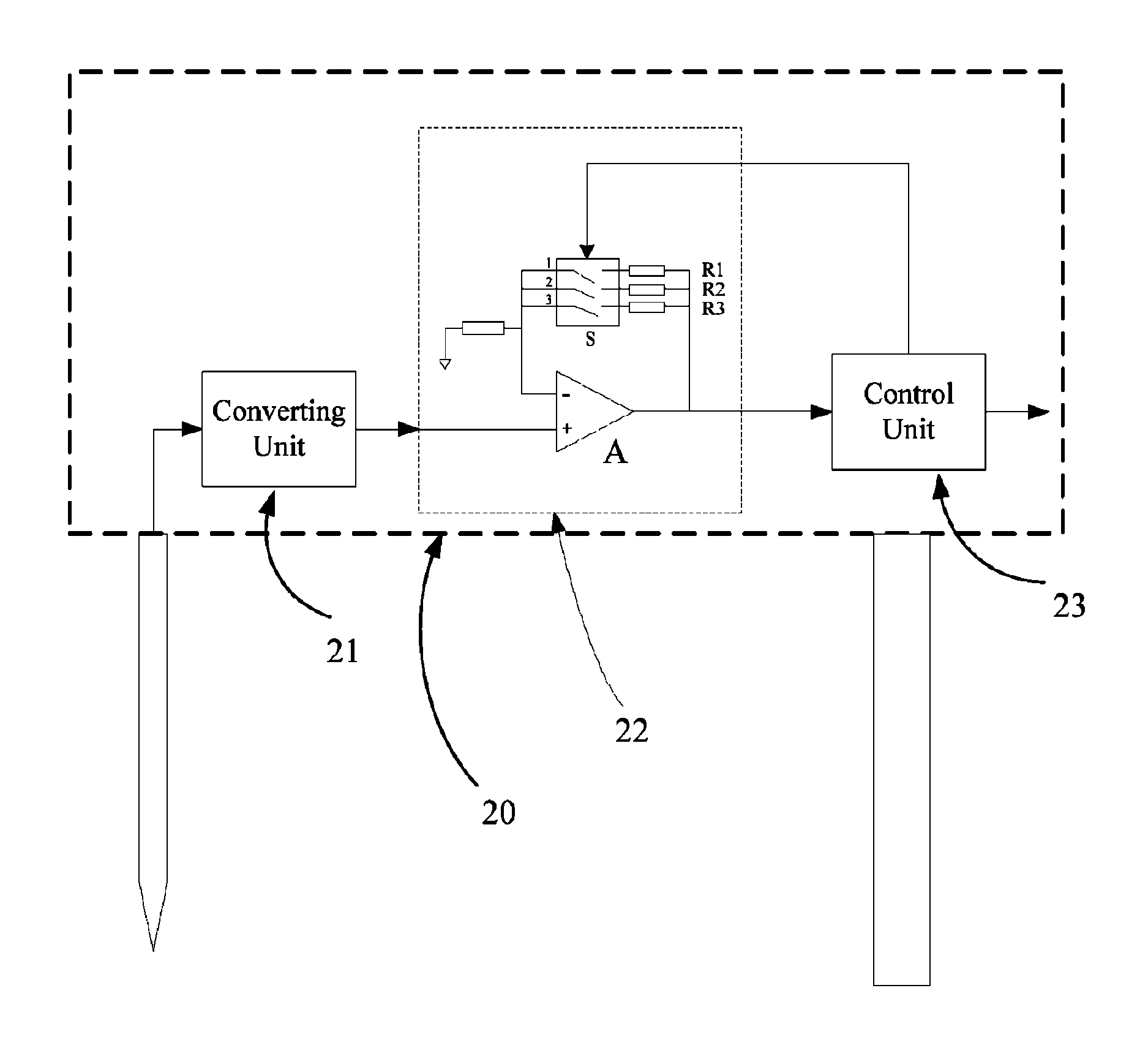
Method used


Image

  • Liquid level detecting device and sample applying system
  • Liquid level detecting device and sample applying system
  • Liquid level detecting device and sample applying system

Examples


Embodiment Construction

[0018]Various embodiments will hereinafter be further described in details by specific implementations with reference to the drawings.

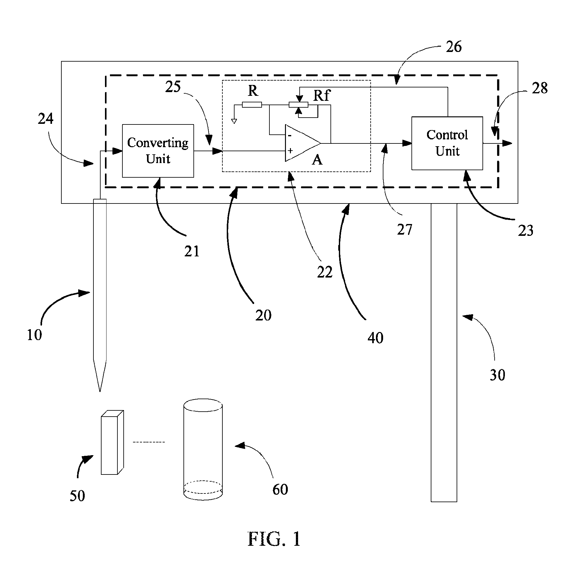
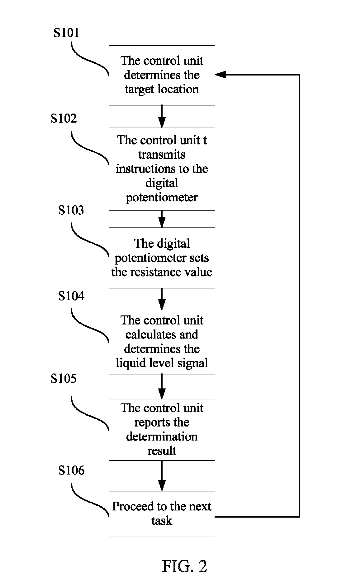
[0019]In some embodiments, the liquid level detecting device sets the gain factor of the amplifying unit according to the environment where the sampling needle locates or operates, optionally amplifies liquid level signals from the sampling needle according to the set gain, and then determines whether the sampling needle contacts the surface based at least in part upon the optionally amplified liquid level signals.

[0020]In some embodiments where the environment that the sampling needle is located or operates exhibits an influence, which exceeds a predetermined threshold level, on the capacitance of the sampling needle and thereby renders the change in the capacitance of the sampling needle significant, the gain of the amplifying unit may be lowered to a predetermined level to determine whether the sampling needle detects the liquid level while ensurin...


PUM


Abstract

Various embodiments disclose a liquid level detecting device and method, which comprises: a control unit configured to output control instructions corresponding to environmental information according to the environmental information of a location of a sampling needle; an amplifying unit configured to set a gain according to the control instructions; a converting unit configured to receive and convert a capacitance signal from the sampling needle to a voltage signal; the amplifying unit receives the voltage signal and amplifies the voltage signal according to the gain; the control unit receives the amplified voltage signal and compares the amplified voltage signals with a preset voltage threshold to determine whether the sampling needle contacts the liquid level. Some embodiments further disclose a sample application system. Various embodiments consider both sensitivity and reliability of a detection system and is adaptable to various detection environments.

Description

CROSS-REFERENCE TO RELATED APPLICATIONS[0001]This application claims priority to Chinese Patent Application No. 200910106574.6, filed on Apr. 9, 2009, which is hereby incorporated by reference in its entirety.FIELD OF INVENTION[0002]Various embodiments relate to a methods and apparatus of a sample applying system. Some embodiments are directed at a liquid level detecting device in a sample applying system.BACKGROUND[0003]In the field of medicine, a sample applying system or a sampling system (hereinafter a sampling system) is often needed for sampling and for adding and / or pipetting samples and / or reaction solution. In a sample applying system, the location of the sampling needle is positioned based at least in part on the detection of the liquid level. That is, the sampling system preferably stops advancing the sampling needle or device when the sampling needle contacts the object liquid level so as to carry out the next task. This function may be realized by a liquid level detecti...

Claims


Application Information

Patent Timeline
Patent Type & Authority Patents(United States)
IPC IPC(8): G08B21/00
CPCG01F23/263G01F23/265G01F23/266G01F23/268G05B15/02
Inventor DU, PENGCHEN, YUEPINGWENG, YANWEN
Owner SHENZHEN MINDRAY BIO MEDICAL ELECTRONICS CO LTD
Learn More