Device for interferometrically measuring the eye length and the anterior eye segment

a technology of interferometry and eye length, which is applied in the field of devices for interferometry measuring eye length and anterior eye segment, can solve the problems of time-consuming adjustment of eye length and eye length, and the inability of patients to co-operate, and achieve the effect of high reliability and sensitivity

Active Publication Date: 2015-10-20
CARL ZEISS MEDITEC AG
View PDF17 Cites 0 Cited by
  • Summary
  • Abstract
  • Description
  • Claims
  • Application Information

AI Technical Summary

Benefits of technology

[0017]Embodiments of the present invention implement an approach for interferometrically measuring the anterior portion of the eye which is much less sensitive to adjustment compared to the prior art, and which allows measurement of a higher proportion of eyes with visual defects. It is the aim that the approach to be developed is characterized by high reliability and sensitivity.
[0019]The device according to the invention relates to the field of ophthalmology, and is provided for the simultaneous interferometric measurement of the eye length and the anterior portion of the eye, the measuring device being characterized by high reliability and sensitivity.

Problems solved by technology

This results, on the one hand, from aberrations of the eye, for example due to the fact that radii of curvature of the individual ocular media are not uniform, the lens of the eye is tilted, the retina is not situated in the focus of the lens of the eye, and many other factors.
In clinical practice, adjusting these conditions is time-consuming, and with uncooperative patients is sometimes not possible at all.
Patients who have already received an artificial lens cannot be measured in this manner.
However, in order to record measuring variables in the anterior portion of the eye, such as the depth of the anterior chamber, lens thickness, etc. using the same method, there is the problem that light reflected from the particular boundary surface must be spatially superimposed on the reference reflection (usually the corneal reflection) in such a way that the interference of the partial beams is measurable.
In addition, the fixation light always appears to the patient at an infinite point, which may prove to be disadvantageous.
This method is extremely time-consuming, and also does not provide the desired results in all patients.
This method is laborious for use in everyday clinical practice.

Method used


Image

  • Device for interferometrically measuring the eye length and the anterior eye segment
  • Device for interferometrically measuring the eye length and the anterior eye segment
  • Device for interferometrically measuring the eye length and the anterior eye segment

Examples


Embodiment Construction

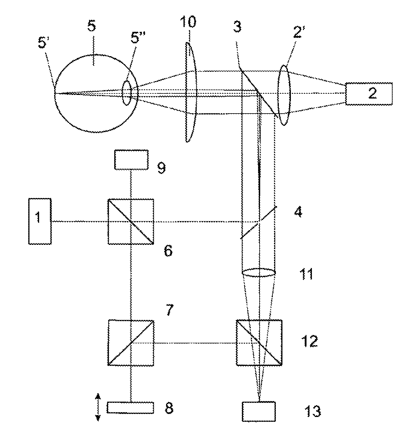
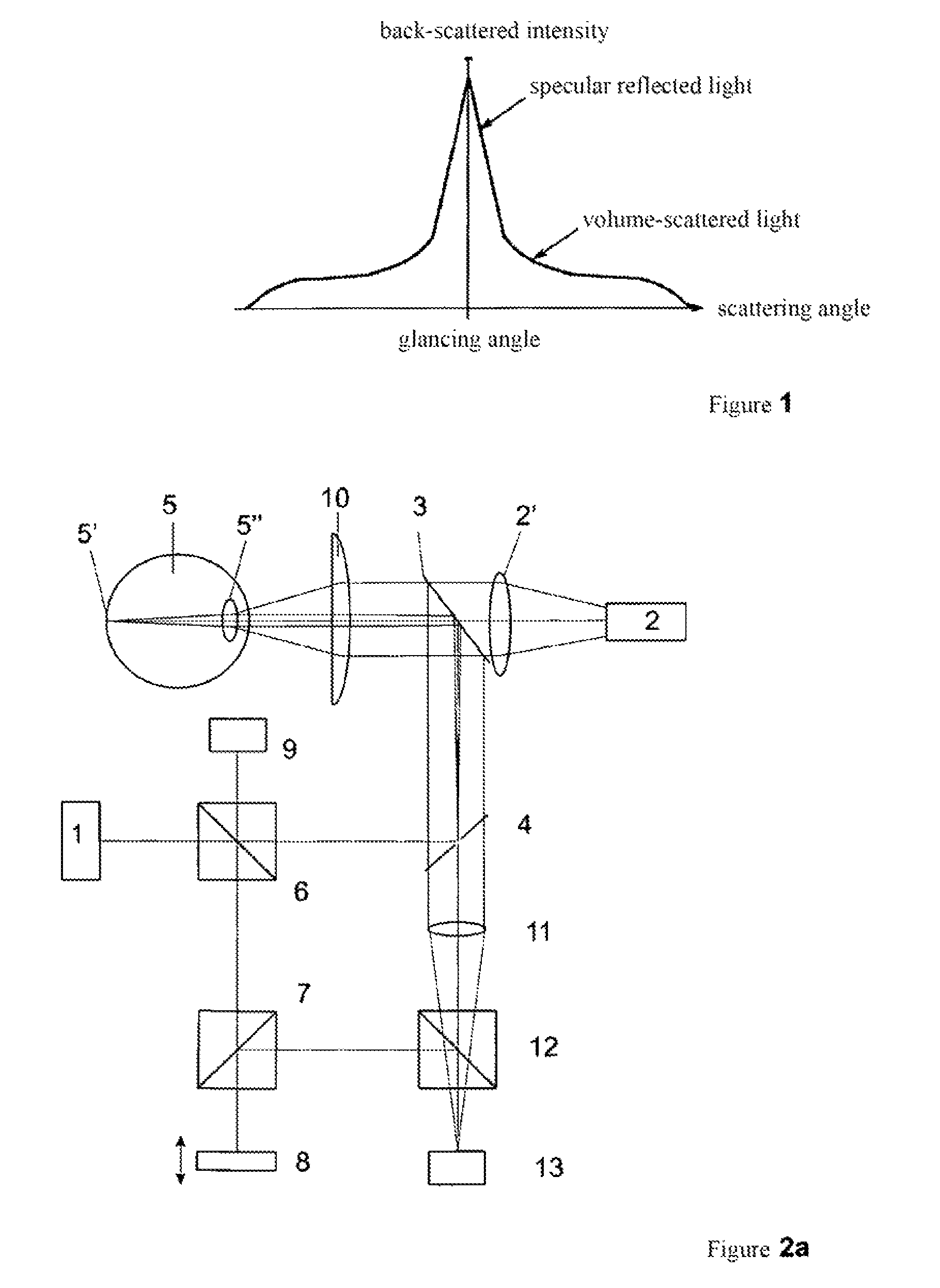
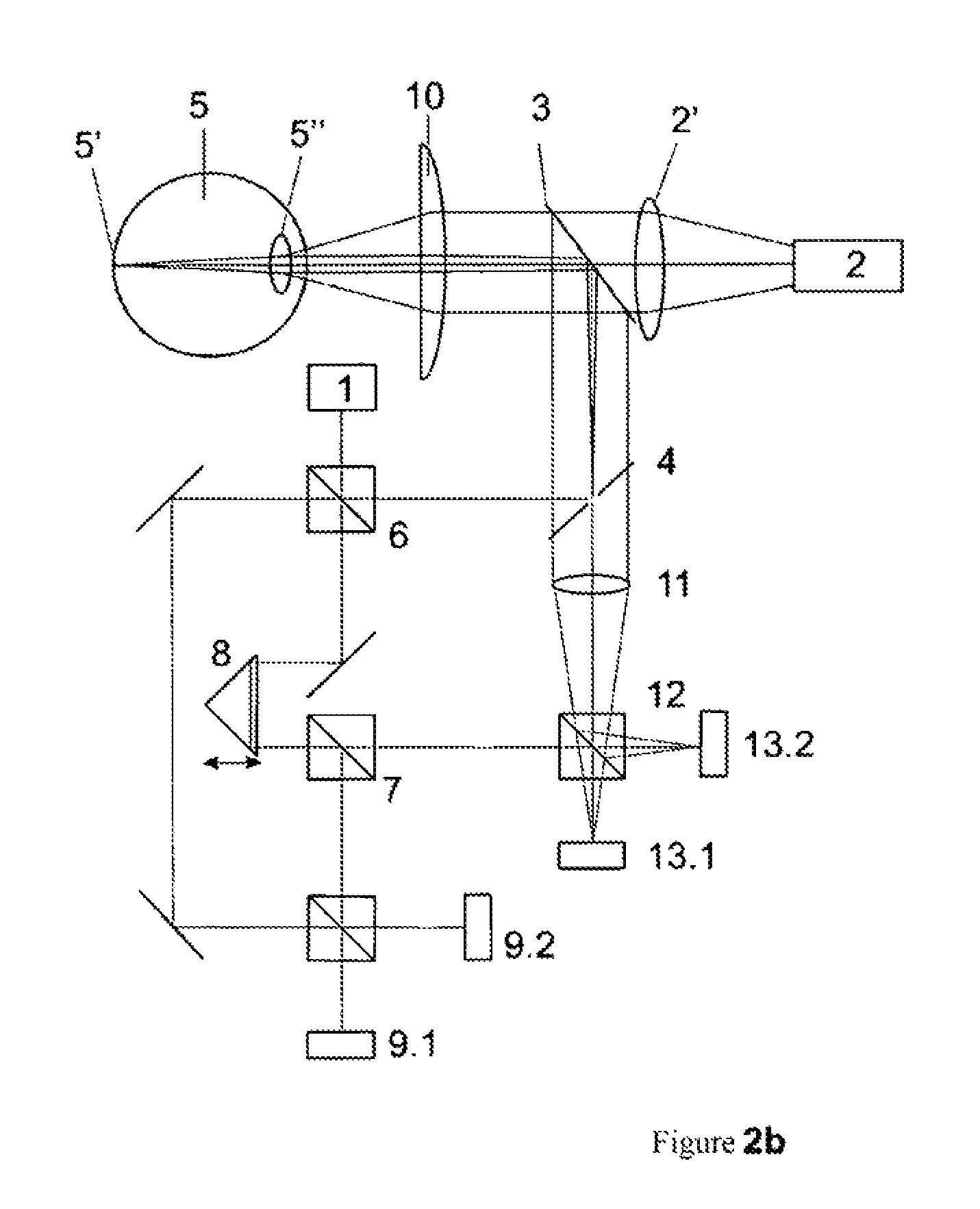
[0026]A device according to an example embodiment of the invention for interferometrically measuring the eye length and the anterior portion of the eye includes an illumination source, at least one interferometric measuring system having an external reference, various optical imaging systems, and a control and evaluation unit. The illumination source has high spatial coherence and low temporal coherence. The illumination device emits light from the NIR range having a wavelength of 700-1000 nm, for example. Furthermore, an optical imaging system is situated in front of the eye in such a way that the illumination light strikes the eye as an approximately collimated beam.

[0027]In this regard, it is advantageous that the device according to the invention has at least one image sensor, which although not absolutely necessary for the function, is practical as an adjustment aid. For coupling the illumination path and the observation beam path, the device has an appropriate beam splitter.

[0...


PUM


Abstract

The invention relates to a solution for interferometrically measuring the eye length and the anterior eye segment after the optical axis of the measuring system has been aligned with the optical axis of an eye. The device according to the invention for interferometrically measuring the eye length and the anterior eye segment consists of an illumination source, at least one interferometric measuring array with external reference, diverse optical imaging systems, and a control and evaluation unit. The illumination source has high spatial coherence and low coherence of time. Preferably, light is emitted by the illumination device from the NIR range, having a wavelength of 700-1000 nm, for example. Furthermore, an optical imaging system is arranged in front of the eye such that the illumination light impinges on the eye as a nearly collimated beam.

Description

RELATED APPLICATIONS[0001]The present application is a National Phase entry of PCT Application No. PCT / EP2011 / 006395, filed Dec. 17, 2011, which claims priority from DE Application No. 10 2010 055 350.6, filed Dec. 20, 2010, which applications are hereby incorporated by reference herein in their entirety.FIELD OF THE INVENTION[0002]The present invention relates to an approach for interferometrically measuring the eye length and the anterior portion of the eye after the optical axis of the measuring system has been aligned with the optical axis of an eye.BACKGROUND[0003]The optical axis of the eye is characterized by the straight line between the centers of curvature of refractive surfaces, while the visual axis refers to the axis extending from the “fovea centralis,” through the nodal point of the eye, to the fixation object. If the various media are reduced by computation to a single medium having average refractive power and spherical curvature, a point in the eye may be indicated...

Claims


Application Information

Patent Timeline
Patent Type & Authority Patents(United States)
IPC IPC(8): A61B3/10A61B3/117G01B9/02
CPCA61B3/1005A61B3/102A61B3/117G01B9/02028
Inventor SCHMITT-MANDERBACH, TOBIASBUBLITZ, DANIELBERGNER, ROLAND
Owner CARL ZEISS MEDITEC AG
Why Eureka
Try Eureka