Method for producing a shock absorber and shock absorber thus obtained

a technology of shock absorber and elongated section, which is applied in the direction of bumpers, vehicular safety arrangments, transportation and packaging, etc., to achieve the effect of improving mechanical features and increasing the relative resistance of the material of the wall of the elongated section

Active Publication Date: 2013-01-29
AUTOTECH ENG SL
View PDF20 Cites 6 Cited by
  • Summary
  • Abstract
  • Description
  • Claims
  • Application Information

AI Technical Summary

Benefits of technology

[0018]Preferably, the mentioned step of elongating at least part of a section of the provisional hollow portion of the partially formed part is carried out by a lathe spinning technique, also known as flowturning or embossing with a flow of the material which can be a direct or reverse cylindrical spinning or a conical spinning depending on the cylindrical or conical shape respectively of the section to be elongated. In any of the two cases, the thickness of the wall of the section which is elongated becomes thinner as a result of the spinning operation. Also as result of the spinning, the relative resistance of the material of the wall of the elongated section is increased and its mechanical features are improved.

Problems solved by technology

It must be taken into account that the expression “substantially equal” referred to the thickness of the walls of the part partially formed by drawing in relation to the initial thickness of the planar sheet part intends covering the slight variations experienced as an inevitable result of the process, but in any case they are not significant and are not a desired result.

Method used


Image

  • Method for producing a shock absorber and shock absorber thus obtained
  • Method for producing a shock absorber and shock absorber thus obtained
  • Method for producing a shock absorber and shock absorber thus obtained

Examples


Embodiment Construction

[0033]The same alphanumeric references have been used throughout the following detailed description to designate same or equivalent elements in the different embodiments shown.

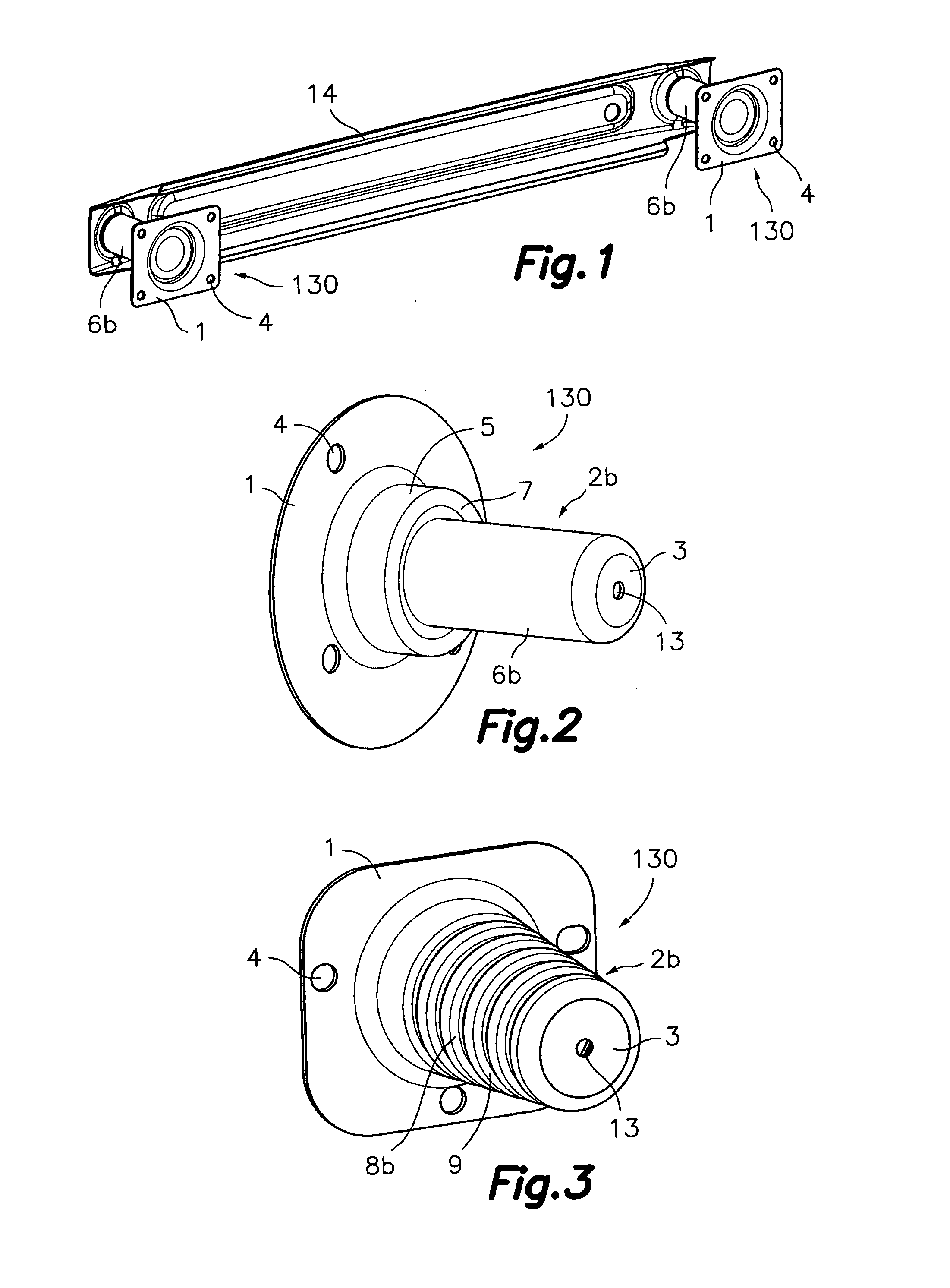
[0034]FIG. 1 illustrates a conventional type bumper crossbeam 14, in the ends of which there are fixed shock absorbers 130 according to an embodiment of the present invention similar to the one shown in FIG. 2.

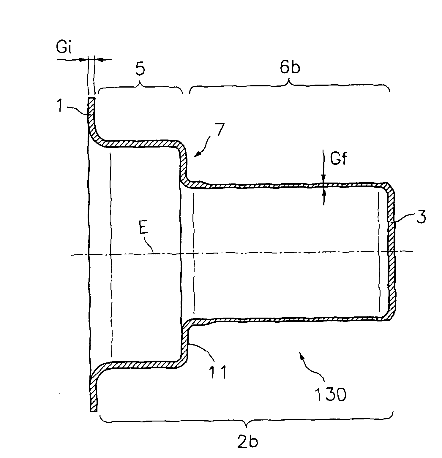
[0035]The shock absorber 130 of FIG. 2 is a single part and comprises a plate 1 from which there extends an elongated hollow portion 2b having a revolution shape with respect to an axis perpendicular to said plate 1, and an end wall 3 arranged parallel to the plate 1 closing the elongated hollow portion 2b in an end opposite to plate 1. The mentioned elongated hollow portion 2b comprises a substantially cylindrical first section 5 extending from plate 1, a substantially cylindrical elongated second section 6b connected to the end wall 3 and a transition section 7 connecting said first and second sections...


PUM

PropertyMeasurementUnit
coning angleaaaaaaaaaa
thicknessaaaaaaaaaa
diameteraaaaaaaaaa

Abstract

The method includes providing a planar sheet part; forming the planar sheet part by drawing or conical spinning to the shape of a partially formed part made up of a plate and a provisional hollow portion extending from the plate with a revolution shape with respect to an axis perpendicular to the plate, and an end wall closing an end of the provisional hollow portion opposite to the plate; and elongating a section of the provisional hollow portion by cylindrical or conical spinning. The shock absorber is integral with a plate and an elongated hollow portion extending from the plate with a revolution shape. A section of the elongated hollow portion has a thickness that is thinner than the thickness of the plate.

Description

[0001]This application is a Continuation Application of PCT International Application No. PCT / ES2006 / 000432 filed Jul. 21, 2006.FIELD OF THE ART[0002]The present invention relates to a method for producing a shock absorber and a shock absorber obtained by said method. The shock absorber has an application in the automotive field as a bumper crossbeam support in a vehicle.BACKGROUND OF THE INVENTION[0003]U.S. Pat. No. 6,554,333 discloses a shock absorber comprising an elongated hollow body with a revolution shape with respect to an axis and defining different stepped tube sections of decreasing diameters. Between every two tube sections of different diameters, there is a transition section defining a step with a perimetric wave provided to facilitate the telescopic insertion of one section into the other in case of impact. The end of the larger diameter tube section is joined by welding to a connection plate or member adapted to be fixed in a releasable manner to the vehicle structur...

Claims


Application Information

Patent Timeline
Patent Type & Authority Patents(United States)
IPC IPC(8): B21D22/00
CPCB60R19/34F16F7/12Y10T29/49622
Inventor PASCUAL BARRIO, IDOYAPERARNAU RAMOS, FRANCESCGARCIA BONILLA, ISABEL
Owner AUTOTECH ENG SL
Why Eureka
Try Eureka