Stitch distribution control system for tufting machines
What is AI technical title?
AI technical title is built by Patsnap AI team. It summarizes the technical point description of the patent document.
a technology of tufting machine and distribution control system, which is applied in the field of tufting machine, can solve the problems of restricted production rate of such machines and limited special applications of specialized color patterning machines, and achieve the effect of sufficient enhanced density
Active Publication Date: 2013-01-29
CARD MONROE
View PDF165 Cites 60 Cited by
Summary
Abstract
Description
Claims
Application Information
AI Technical Summary
This helps you quickly interpret patents by identifying the three key elements:
Problems solved by technology
Method used
Benefits of technology
Benefits of technology
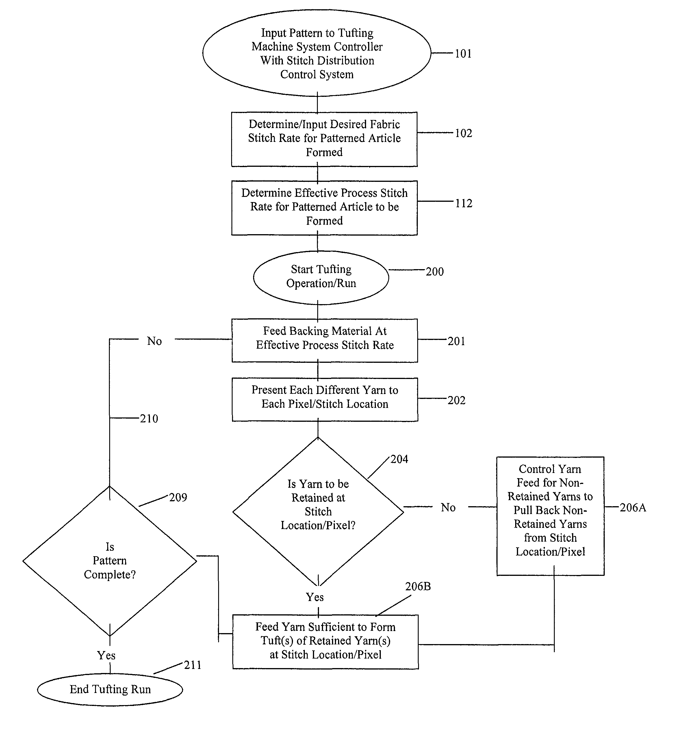
[0006]Briefly described, the present invention generally relates to a yarn stitch or color distribution control system for a tufting machine for use in controlling placement and density of yarns or stitches with enhanced selectivity so as to enable formation of patterned tufted articles, such as carpets having a variety of pattern effects and / or colors, including the formation of substantially free-flowing multi-color patterns and / or carpets with a woven or loom formed appearance. The tufting machine with the stitch distribution control system of the present invention typically will include a tufting machine controller for controlling the operative elements of the tufting machine, as well as operating the stitch distribution control system according to the present invention for forming a desired scanned and / or designed pattern. The pattern can include various desired pattern effects, including different pile heights, cut and / or loop pile tufts in various tuft rows, and other textured effects, as well as the placement of various color yarns so as to be visible at selected locations across the backing to thus provide a desired density of retained colors / stitches per square inch. For example, the pattern can contain all loop pile tufts, all cut pile tufts, and / or combinations of cut and loop pile tufts, including variable pile height tufts and other sculptured or pattern texture effects.
[0008]The stitch distribution control system according to the present invention will not only operate to control the tufting operations of the tufting machine, but further can include image recognition software to enable the stitch distribution control system to read and recognize scanned and / or designed pattern images including finished carpet designs with texture information such as pile heights, loop and / or cut pile tuft placement, drawings, photographs, etc., in addition to receiving input pattern instructions. The stitch distribution control system can automatically generate a pattern program file including a map or field of pattern pixels or tuft / stitch locations for the yarns / stitches of the scanned and / or designed pattern, as well as can calculate steps or parameters for controlling yarn feed, backing feed and the other operative elements of the tufting machine to form in the desired scanned and / or designed pattern. The stitch distribution control system further can recognize and correlate pattern colors to corresponding positions in a creel for the tufting machine based upon the thread-up of colors of the needle bar(s) in order to optimize the use of the creel, and additionally will automatically calculate a cam / shift profile (or select a pre-programmed cam profile as needed), and will calculate an effective or operative process stitch rate at which the pattern will be run to achieve the appearance of a desired fabric stitch rate or pattern density in the finished tufted article.
Problems solved by technology
A problem exists, however, with such specialty tufting machines for individually placing yarns, in that the production rates of such machines generally are restricted as the yarns are placed individually in the backing material by the single needle or as the backing feed direction is changed.
As a consequence, such specialized color patterning machines typically are limited to special applications such as formation of patterned rugs or carpets of limited or reduced sizes.
Method used
Image
Click on the blue label to locate the original text in one second.
Reading with bidirectional positioning of images and text.
Examples
Embodiment Construction
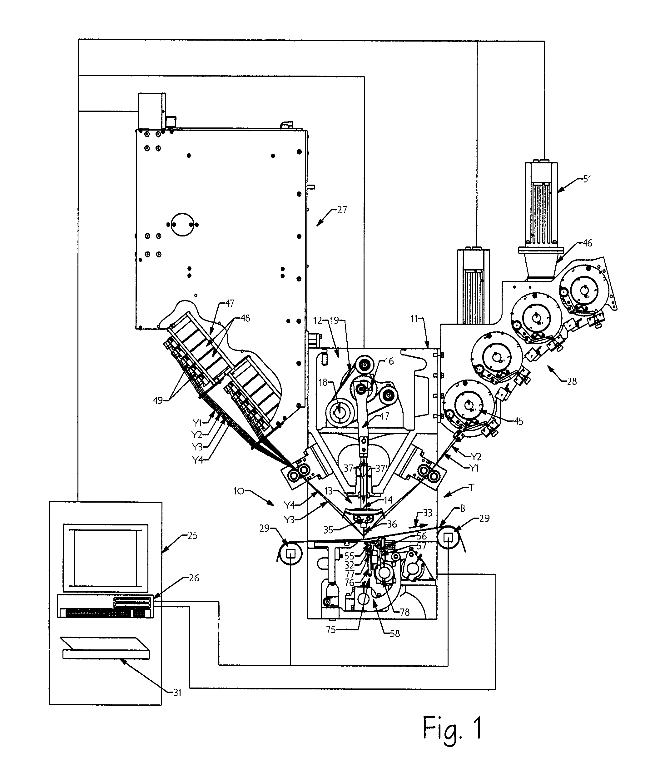
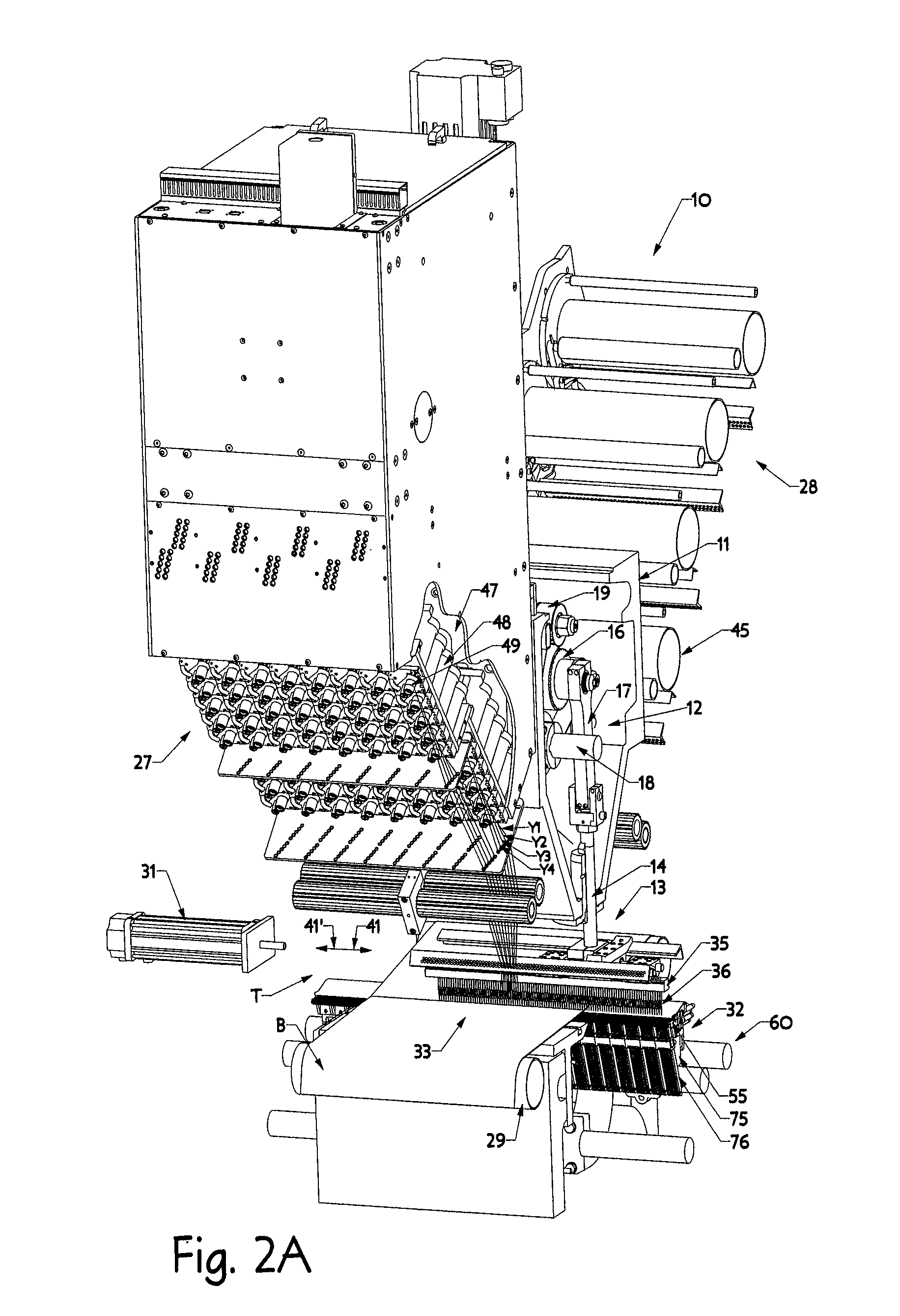
[0027]Referring now to the drawings in which like numerals indicate like parts throughout the several views, in accordance with one example embodiment of the yarn stitch or color distribution control system according to the principles of the present invention, as generally illustrated in FIGS. 1-5C, a tufting machine 10 is provided for controlling placement and density of individual stitches or yarns Y1-Y4, etc., at desired stitch locations in the backing material B and with enhanced selectivity so as to enable the formation of tufted articles having a desired density of retained stitches per square inch, with a variety of varying or free-flowing pattern effects selectively formed therein. Such pattern effects can include formation of all loop pile tufts, all cut pile tufts, or combinations of cut and loop pile tufts in the backing material, including being formed in the same tuft rows, formation of varying pile heights, and formation of multi-color patterns of various geometric and...
PUM
Abstract
A stitch distribution control system for a tufting machine for controlling placement of yarns being fed to the needles of the tufting machine by yarn feed mechanisms to form a desired pattern. A backing material is fed through the tufting machine at an increased stitch rate as the needles are shifted according to calculated pattern steps. A series of loopers or hooks engage and pick loops of yarns from the needles. The yarn feed mechanisms further can be controlled so that selected loops of yarns can be back-robbed so as to be hidden from view in the finished patterned tufted article.
Description
CROSS REFERENCE TO RELATED APPLICATIONS[0001]This application is a continuation-in-part of U.S. patent application Ser. No. 12 / 122,004, entitled YARN COLOR PLACEMENT SYSTEM, filed May 16, 2008, now U.S. Pat. No. 8,141,505 which claims the benefit of U.S. Provisional Application Ser. No. 61 / 029,105, entitled YARN COLOR PLACEMENT SYSTEM, filed Feb. 15, 2008, and further claims the benefit of U.S. Provisional Application Ser. No. 61 / 077,499 entitled COLOR DISTRIBUTION CONTROL SYSTEM FOR TUFTING MACHINES, filed Jul. 2, 2008, of U.S. Provisional Application Ser. No. 61 / 154,597, entitled STITCH DISTRIBUTION CONTROL SYSTEM FOR TUFTING MACHINES, filed Feb. 23, 2009, and of U.S. Provisional Application Ser. No. 61 / 184,993, entitled LEVEL CUT LOOP LOOPER AND CLIP ASSEMBLY, filed Jun. 8, 2009, each of the listed applications being incorporated herein by reference in its entirety.FIELD OF THE INVENTION[0002]The present invention generally relates to tufting machines, and in particular, to a sys...
Claims
Application Information
Patent Timeline
Application Date:The date an application was filed.
Publication Date:The date a patent or application was officially published.
First Publication Date:The earliest publication date of a patent with the same application number.
Issue Date:Publication date of the patent grant document.
PCT Entry Date:The Entry date of PCT National Phase.
Estimated Expiry Date:The statutory expiry date of a patent right according to the Patent Law, and it is the longest term of protection that the patent right can achieve without the termination of the patent right due to other reasons(Term extension factor has been taken into account ).
Invalid Date:Actual expiry date is based on effective date or publication date of legal transaction data of invalid patent.

