Respirator with a breathing tube system

a technology of breathing tube and respirator, which is applied in the direction of respiratory apparatus, electrical apparatus, ohmic-resistance heating, etc., can solve the problems of short-circuit development of forward and return lines, tube damage, etc., and achieve the effect of avoiding local temperature increas

Inactive Publication Date: 2013-01-29
DRAGERWERK AG
View PDF22 Cites 36 Cited by
  • Summary
  • Abstract
  • Description
  • Claims
  • Application Information

AI Technical Summary

Benefits of technology

[0006]The basic object of the present invention is to improve a device with a respirator and a breathing tube system such that a local increase in temperature is avoided during the heating of the tube.
[0012]The breathing tube used especially preferably is an extruded endless tube, which is provided with a predetermined breaking point in such a way that the tube can be divided into an inspiration tube and an expiration tube without the resistance wires being interrupted in the area of the Y-piece. The use of an extruded endless tube also has the advantage that breathing tubes can be cut and adapted to the patient's needs individually.

Problems solved by technology

The drawback of the prior-art breathing tube is that short-circuit may develop within the forward line and the return line in case of damage to the insulation of the resistance wires, which is possibly associated locally with intense heating of the tube.
The tube may become damaged hereby, and leaks, through which breathing gas can escape, may also develop at such a site.

Method used


Image

  • Respirator with a breathing tube system
  • Respirator with a breathing tube system
  • Respirator with a breathing tube system

Examples


Embodiment Construction

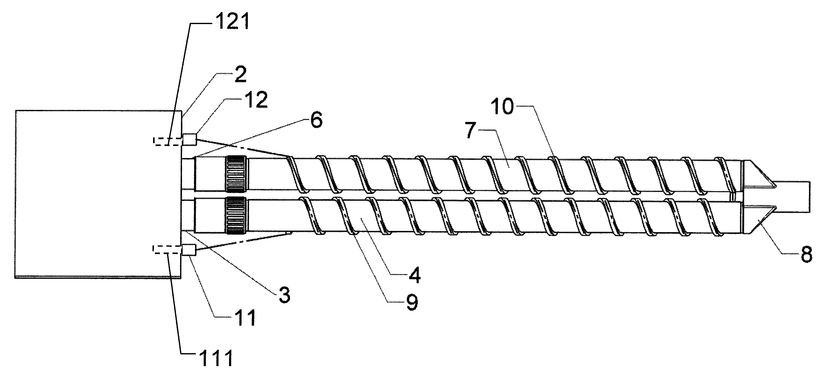
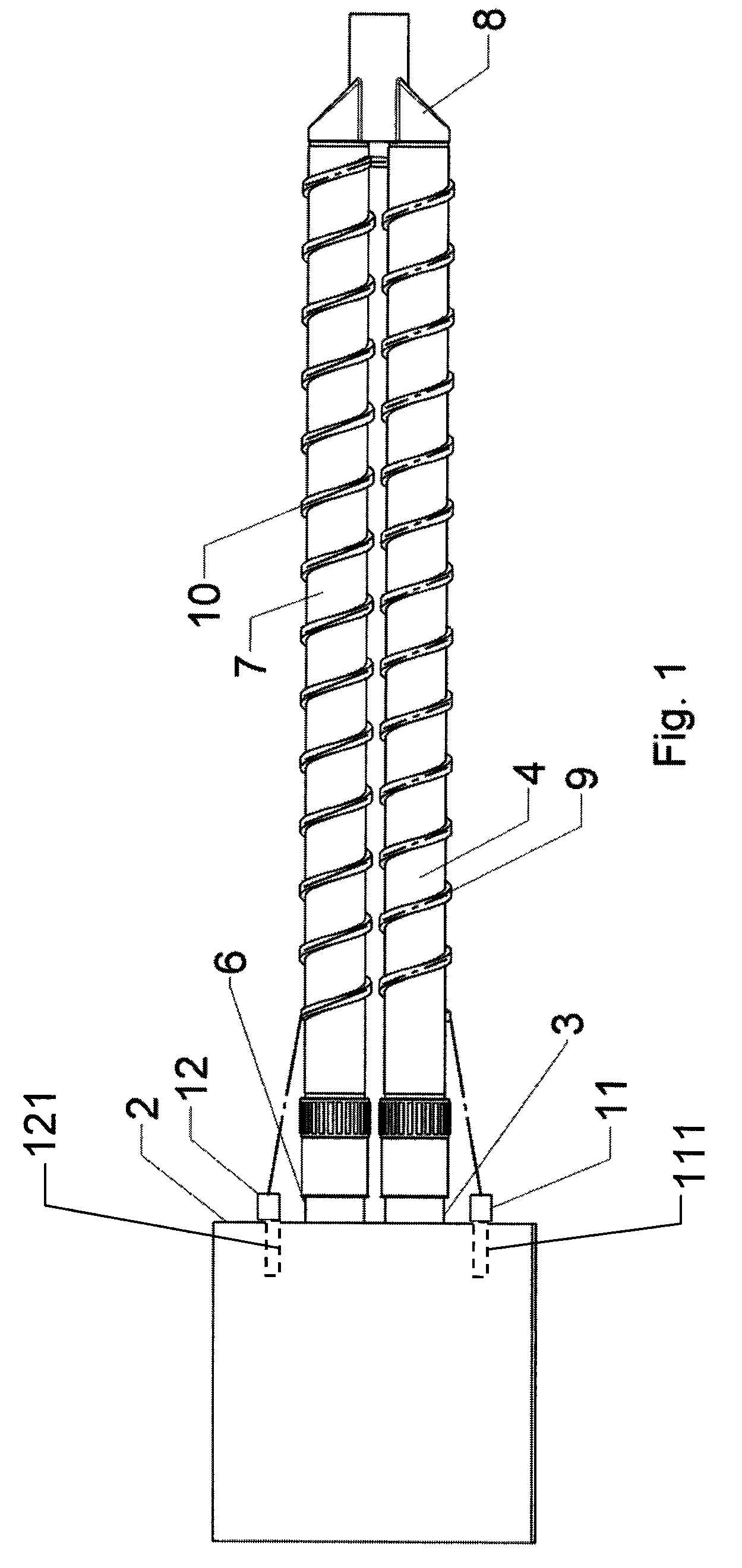
[0025]Referring to the drawings in particular, FIG. 1 schematically shows a respiration system 1, comprising a respirator 2 with an inspiration port 3, an inspiration tube 4, an expiration port 6, an expiration tube 7 and a Y-piece 8 between the inspiration tube 4 and the expiration tube 7. The inspiration tube 4 and the expiration tube 7 have a tube heater in the form of resistance wires 9, 10 fastened helically on the outside. The resistance wires 9, 10 are connected to one another in the form of a series connection and are contacted via single-pole electric plug-type connections 11, 111, 121, 12 at the inspiration port 3 and the expiration port 6. The current flows via a first plug-type part 11, resistance wire 9, resistance wire 10 and a second plug-type part 12. Inspiration tube 4 and expiration tube 7 are parts of an extended endless tube so that the resistance wires are not interrupted.

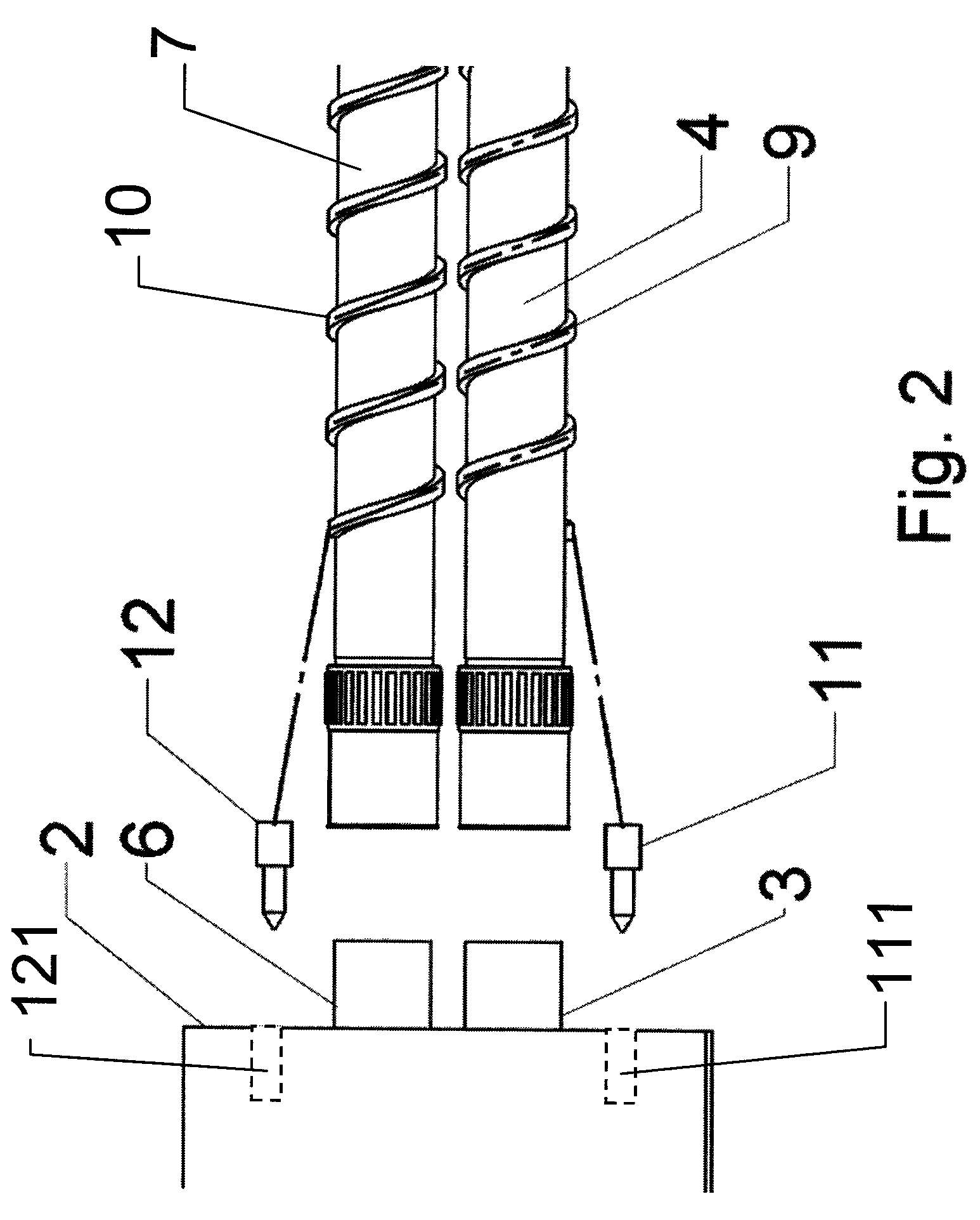
[0026]FIG. 2 illustrates as an example the mechanical and electrical contact at the inspira...


PUM


Abstract

A breathing tube system for connection to a respirator (2), which is provided with a tube heater, avoids a local increase in temperature during the heating of the tube (4, 7). Resistance wires (9, 10) are connected to one another on the breathing tubes (4, 7) in the form of a series connection and are contacted at the respirator (2) in the area of an inspiration port (3) and of an expiration port (6).

Description

CROSS REFERENCE TO RELATED APPLICATIONS[0001]This application claims the benefit of priority under 35 U.S.C. §119 of German Patent Application DE 10 2008 039 137.9 filed Aug. 21, 2008, the entire contents of which are incorporated herein by reference.FIELD OF THE INVENTION[0002]The present invention pertains to a combination of a respirator and a breathing tube system and a respirator for connection to a breathing tube system.BACKGROUND OF THE INVENTION[0003]Patients who are artificially respirated in an intensive care unit receive breathing air, which is adapted to the physiological needs of the patient in terms of temperature and humidity. Active humidifiers, which heat and humidify the breathing gas, are used for this. A water-filled container, through which the gas to be inspired is sent and is enriched with moisture, is located within the humidifier. The breathing tubes are usually provided with a tube heater to prevent condensation of moisture within the breathing tube system....

Claims


Application Information

Patent Timeline
Patent Type & Authority Patents(United States)
IPC IPC(8): A61M16/00A62B7/00F24J3/00H05B3/00
CPCA61M16/0875A61M16/1095A61M16/0833A61M16/16A61M16/1075
Inventor KOULECHOV, KIRILLTAPPEHORN, LUDGER
Owner DRAGERWERK AG
Why Eureka
Try Eureka