
Method for selective-regulating spraying liquid and a device for carrying out said method

a spraying liquid and selective regulation technology, applied in the direction of mixers, lighting and heating apparatus, applications, etc., can solve the problem of becoming more difficult to change the trajectory of the spraying liquid

Inactive Publication Date: 2013-01-29
NADMITOV SERGEI VIKTOROVICH
View PDF8 Cites 0 Cited by
  • Summary
  • Abstract
  • Description
  • Claims
  • Application Information

AI Technical Summary

Benefits of technology

The invention is about a new way to spray liquid that results in a more homogeneous distribution of particles. Unlike previous methods, this approach involves spraying the liquid in a way that causes the particles to separate and remove them simultaneously in the spray cone. This has been shown to be more efficient in solving this problem. The invention is based on a mathematical model that shows the best way to spray liquid to achieve maximum particle homogenization.

Problems solved by technology

As a particle of a liquid accelerates, it becomes more difficult to change its trajectory.

Method used


Image

  • Method for selective-regulating spraying liquid and a device for carrying out said method
  • Method for selective-regulating spraying liquid and a device for carrying out said method
  • Method for selective-regulating spraying liquid and a device for carrying out said method

Examples


Embodiment Construction

[0038]While the invention may be susceptible to embodiment in different forms, there are shown in the drawings, and will be described in detail herein, specific embodiments of the present invention, with the understanding that the present disclosure is to be considered an exemplification of the principles of the invention, and is not intended to limit the invention to that as illustrated and described herein.

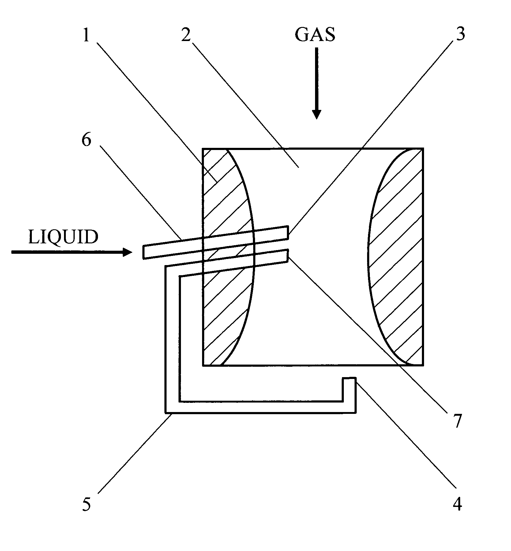
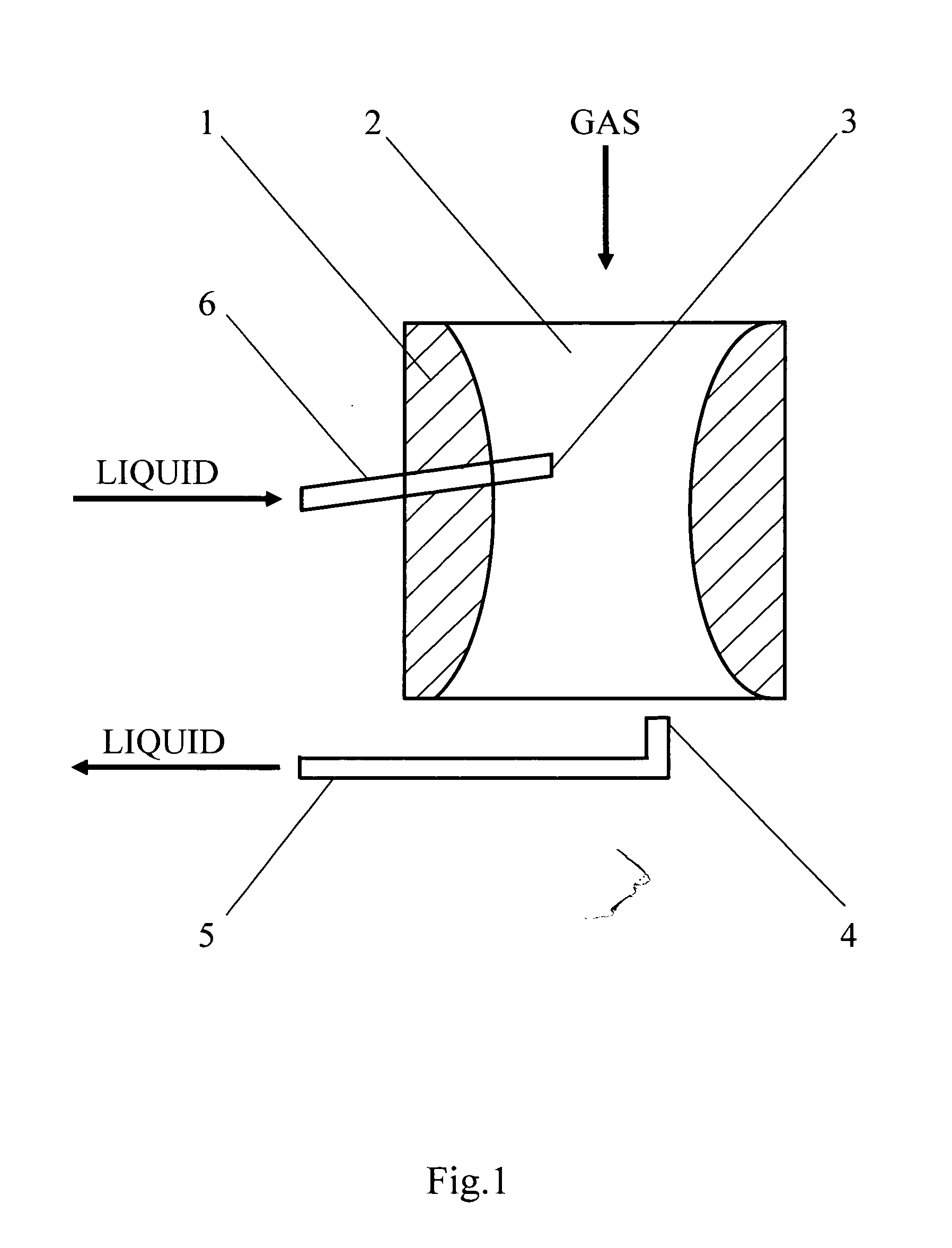
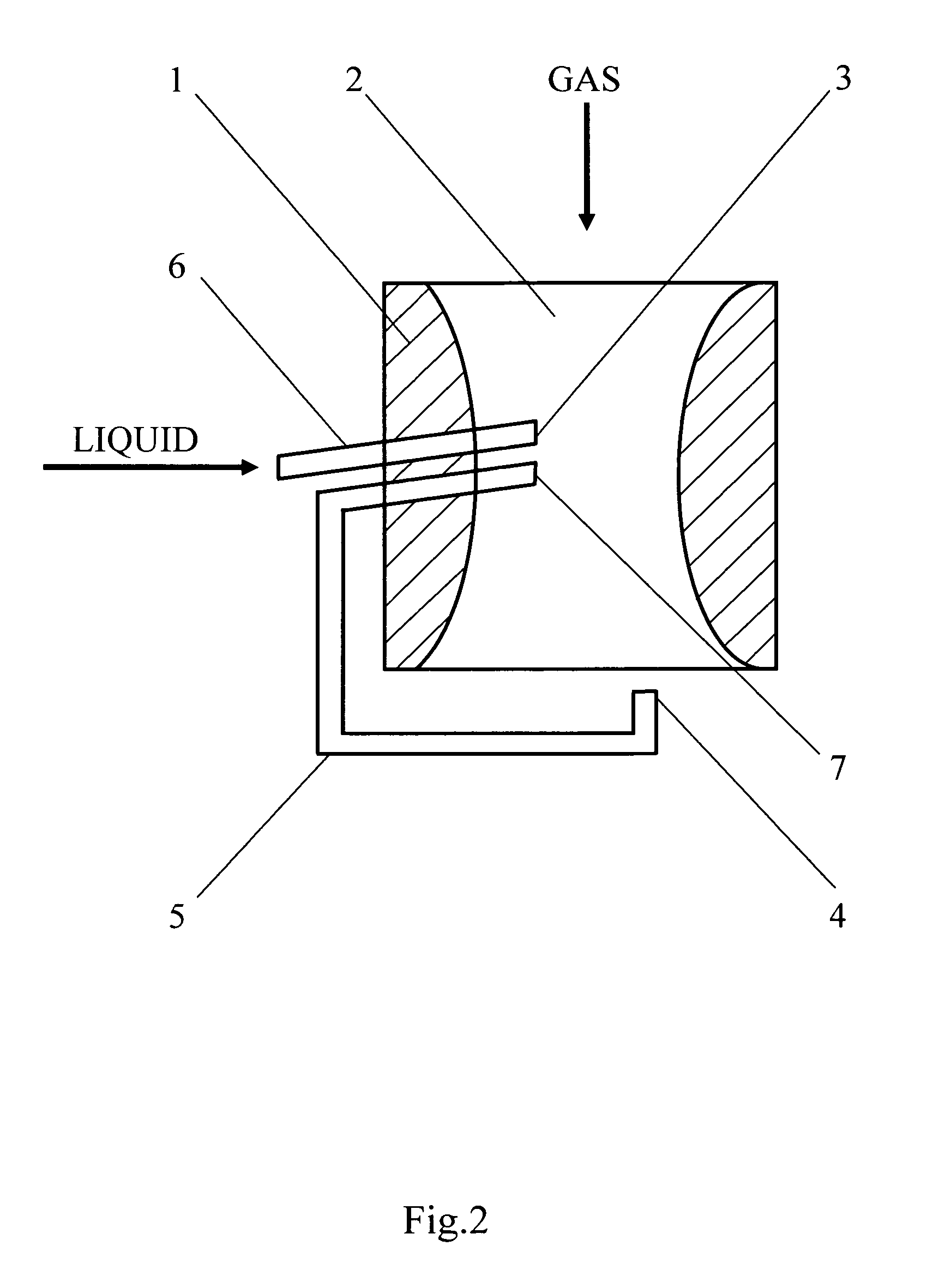
[0039]Therefore, according to variant No. 1 of the present invention, the inventive device comprises: a body (1) with an internal channel (2) capable of creating a laminar unidirectional gas flow having a direction, said internal channel (2) having an intake end for entering said gas flow, and a discharge end for exiting said gas flow; a liquid feed pipe (6) for supplying said liquid into said internal channel (2), said liquid feed pipe (6) having an end furnished with a spray nozzle (3) placed within said internal channel (2) at a predetermined angle to said direction of the ga...


PUM

PropertyMeasurementUnit
angleaaaaaaaaaa
sizesaaaaaaaaaa
particle sizeaaaaaaaaaa

Abstract

The invention relates to methods and devices for spraying liquid during production processes requiring a uniform dispersion mixture, in particular in internal combustion engines requiring a fine fuel-air mixture, in the chemical industry for apparatuses for rinsing gas with liquid, which require a uniform coarse-dispersion mixture for reducing the drop entrainment of a rinsing liquid. The inventive method consists in collecting, during the liquid spraying, which is carried out by injecting a liquid at an angle to a gas flow, particles in those sectors of the spray cone that are appropriate to particles of specified sizes. The liquid spraying and collecting processes are carried out at one section of a laminar unidirectional gas flow. The collected particles form, when accumulated, a liquid that is returned for re-spraying. The inventive device comprises a body (1) with an internal channel (2) for providing a laminar unidirectional gas flow, a spray nozzle (3) which is placed at an angle to the gas flow direction and is connected to a liquid feed pipe (6) and a collector for particles (4) which is made and placed in such a manner that it is able to collect particles in those sectors of the spray cone that are appropriate to particles of specified sizes. In the first variant, the collector is connected to a pipe for returning the liquid for re-spraying (5), and in the second variant, the collector is connected to an additional spray nozzle (7) made in the internal channel of the body.

Description

CROSS-REFERENCE TO RELATED APPLICATIONS[0001]This application is a U.S. national stage application of a PCT application PCT / RU2008 / 000578 filed on 28 Aug. 2008, published as WO / 2009 / 038498, whose disclosure is incorporated herein in its entirety by reference, which PCT application claims priority of a Russian Federation application RU2007134923 filed on 19 Sep. 2007.FIELD OF THE INVENTION[0002]The invention relates to methods and devices for spraying liquid during production processes requiring a uniform dispersion mixture, in particular in internal combustion engines requiring a fine fuel-air mixture, in the chemical industry for apparatuses for rinsing gas with liquid that require a uniform coarse-dispersion mixture for reducing the drop entrainment of a rinsing liquid.BACKGROUND OF THE INVENTION[0003]Many devices are known for spraying liquid during production processes that use the method of pneumatic spraying and belong to jet devices. Jet devices are those where a process of e...

Claims


Application Information

Patent Timeline
Patent Type & Authority Patents(United States)
IPC IPC(8): B05B7/00B01F25/70
CPCB01F3/04049F23D11/40B01F5/0652B01F5/0646B01F23/2132B01F25/4335B01F25/433
Inventor NADMITOV, SERGEI VIKTOROVICH
Owner NADMITOV SERGEI VIKTOROVICH
Learn More