Side visor for automobile

a side visor and automobile technology, applied in the field of side visors, can solve the problems of increasing the manpower for manufacturing the side visor, increasing the number of side visor parts, increasing the wind noise, etc., and achieves the effects of increasing wind noise, increasing wind noise, and scarce wind nois

Inactive Publication Date: 2013-01-29
HAYASHI KAGAKU INDS
View PDF11 Cites 17 Cited by
  • Summary
  • Abstract
  • Description
  • Claims
  • Application Information

AI Technical Summary

Benefits of technology

[0014]A first object of the present invention is to provide a side visor for automobile capable of ventilating a cabin efficiently without increase in the number of parts and the manpower for manufacture and with scarce generation of wind noise. A second object of the present invention is to provide a side visor for automobile capable of rapidly discharging the air in the cabin through a through hole while preventing the air in the cabin discharged to the outside of vehicle through the through hole from intruding again into the cabin and while restraining the strength near the through hole from decreasing.

Problems solved by technology

For the above-described conventional side visor, the gap between the lower edge of the side visor and the upper edge of the window glass extends relatively long from the front part to the rear part of the side visor, which poses a problem that the air in the cabin discharged through the front gap of the gap between the lower edge of the side visor and the upper edge of the window glass intrudes again into the cabin through a rear gap of the gap between the lower edge of the side visor and the upper edge of the window glass.
Unfortunately, for the conventional side visor for automobile described in Patent Document 1, the grill plate must be welded to the inner wall surface, which poses problems of increased number of parts of the side visor and increased man power for manufacturing the side visor.
Also, for the conventional side visor for automobile described in Patent Document 1, the plurality of fins directed to the outside are projectingly provided at the rear at the front edges of the plurality of the draft ports, which also poses a problem that an eddy current is generated at the rear of each of the fins, which increases wind noise.
On the other hand, for the conventional automobile member for accelerating discharge of interior air described in Patent Document 2, the elongated outer and inner blades and the two or more bridge plates for bridging these blades are required, and these elements must be bonded to each other, which poses problems of increased number of parts of the discharge accelerating member and increased man power for manufacturing the discharge accelerating member.
Also, for the conventional automobile member for accelerating discharge of interior air described in Patent Document 2, in the case where the discharge accelerating member is mounted to the front pillar of a passenger car, which is a cab-behind-engine type automobile, since the angle that the front pillar makes with the flow direction of air flow produced by the running of the passenger car is small, the height of the discharge accelerating member becomes small, and the width for drawing the air in the cabin from the discharge accelerating member becomes narrow, which poses a problem of decreased ventilation efficiency in the cabin.

Method used


Image

  • Side visor for automobile
  • Side visor for automobile
  • Side visor for automobile

Examples


first embodiment

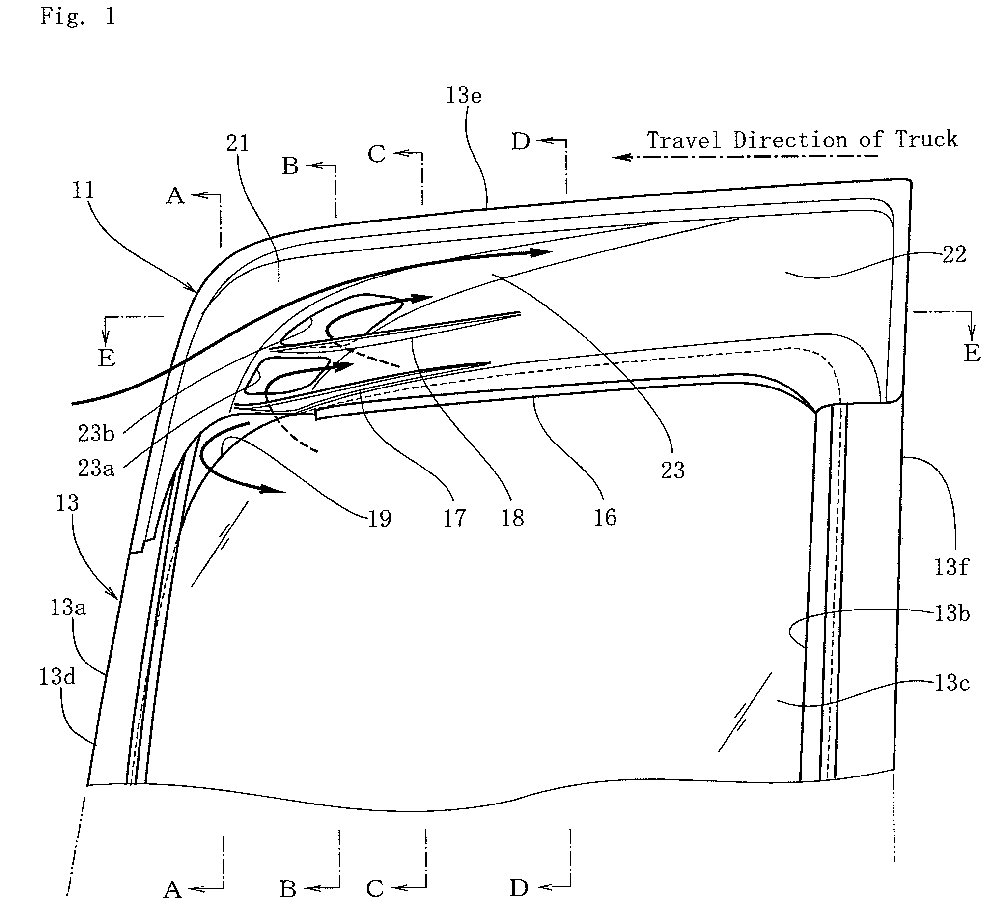
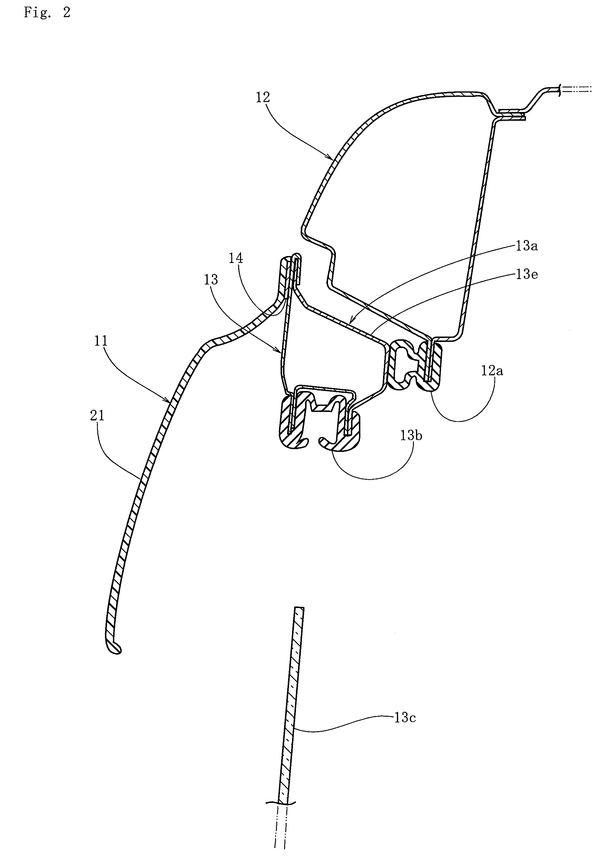
[0053]As shown in FIGS. 8 and 9, a side visor 11 of a first embodiment is mounted to a side door 13 of a cab-over-engine truck 10. Since the side visor 11 is symmetrical in the right-and-left direction with respect to the centerline of vehicle body, the side visor 11 mounted to the side door 13 on the assistant driver's seat side is explained exemplarily, and the explanation of the side visor 11 mounted to the side door 13 on the driver's seat side is omitted (FIG. 8). In the side surface of a cab 12 of the truck 10, a port 12a through which one gets on and off is provided, and this port 12a is closed openably by the side door 13 (FIG. 9). In the upper part of the side door 13, a door window 13b defined by a window frame 13a is formed, and the door window 13b is closed and opened by moving the window glass 13c up and down. The window frame 13a has a front frame part 13d provided on the front side of the side door 13 in such a manner as to be erected so as to be tilted slightly to th...

second embodiment

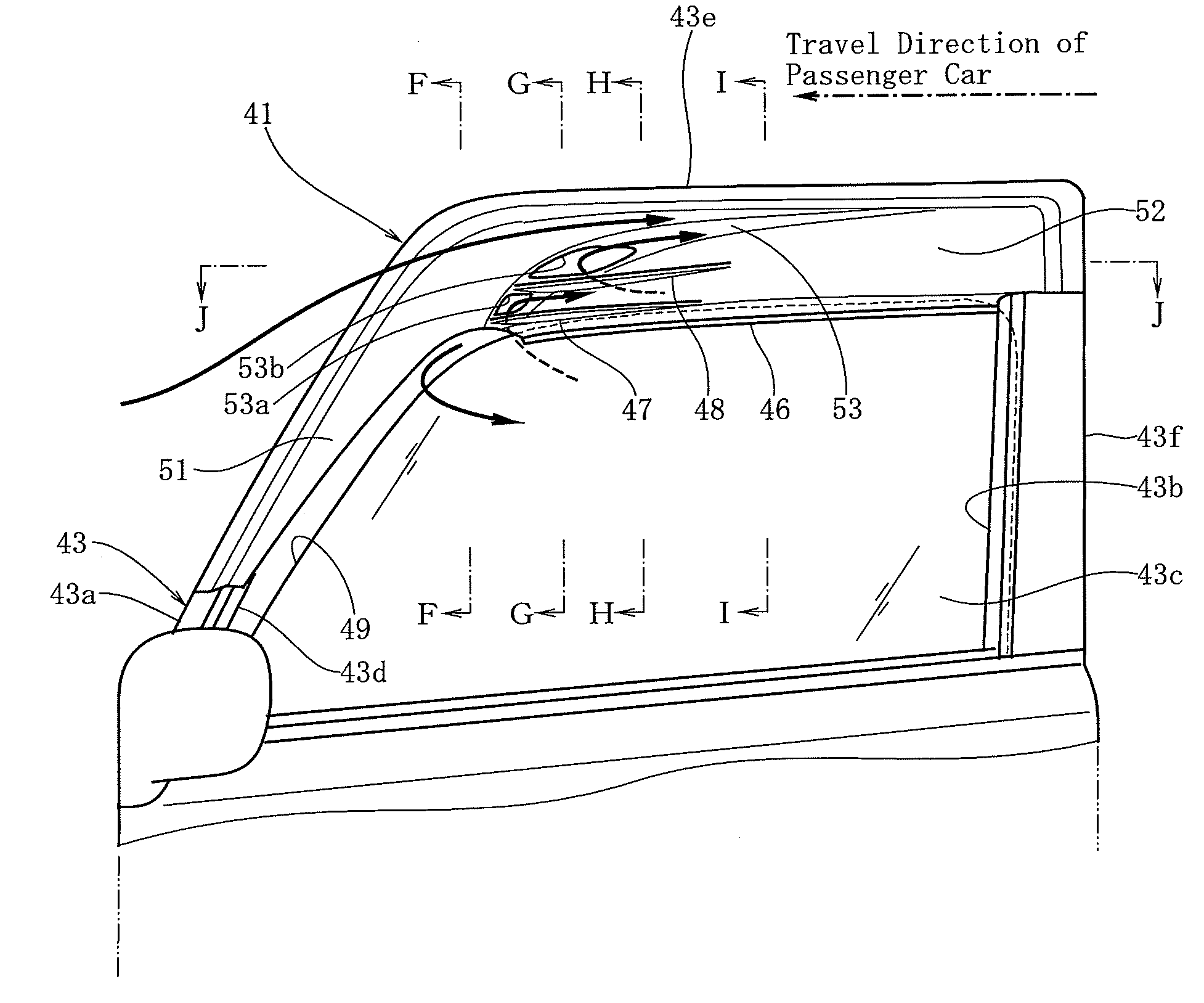
[0060]FIGS. 10 to 17 show a second embodiment of the present invention. In this embodiment, a side visor 41 is mounted to a side door 43 of a cab-behind-engine type passenger car (FIGS. 16 and 17). Since the side visor 41 is symmetrical in the right-and-left direction with respect to the centerline of vehicle body, the side visor 41 mounted to the side door 43 on the assistant driver's seat side is explained exemplarily, and the explanation of the side visor 41 mounted to the side door 43 on the driver's seat side is omitted (FIG. 16). In the front side surface of the passenger car 40, a port 40a through which one gets on and off is provided, and this port 40a is closed openably by the side door 43 (FIG. 17). In the upper part of the side door 43, a door window 43b defined by a window frame 43a is formed, and the door window 43b is closed and opened by moving the window glass 43c up and down. The window frame 43a has a front frame part 43d provided on the front side of the side door...

third embodiment

[0067]FIG. 18 shows a side visor 61 in accordance with a third embodiment of the present invention. In FIG. 18, the same symbols denote the same elements as those in FIG. 10. In this embodiment, a single through hole 63a is provided so as to be curved upward from the front end of a third covering part 63 and extend to the lengthwise direction of the third covering part 63. Also, a single rib 67 is provided from the lower edge of the single through hole 63a to the outer surface of the second covering part 52 so as to extend substantially to the horizontal direction. The rib 67 is formed integrally with the first to third covering parts 51, 52 and 63. The configurations other than those described above are the same as the configurations of the second embodiment. For the side visor 61 for passenger car configured as described above, since the single through hole 63a is provided so as to be curved upward from the front end of the third covering part 63 and extend to the lengthwise direc...


PUM


Abstract

A first covering part of the present invention covers a portion from the front part to the upper part of a door window and expands to the outside in the vehicle width direction, and the lower surface thereof is open. A second covering part covers a portion lower than the first covering part of the upper part of the door window, is provided so as to be on the outside of a window glass and be located on the inside in the vehicle width direction of the lower edge of the first covering part, and is formed so as to gradually approach the window glass from the rear end toward the front end, the lower edge thereof being provided close to the outer surface of the window glass. A third covering part covers a portion between the first and second covering parts in the upper part of the door window by integrally connecting a portion located in the upper part of the door window of the lower edge of the first covering part and the upper edge of the second covering part, and is provided in such a manner as to be curved so as to project to the upside, and extend to the slantwise upside from the front end toward the rear end and extend to the slantwise upside from the upper edge of the second covering part toward the lower edge of the first covering part in the vehicle width direction. In the front part of the third covering part, a plurality of through holes are provided.

Description

BACKGROUND OF THE INVENTION[0001]1. Field of the Invention[0002]The present invention relates to a side visor that is mounted to a window frame of a side door of a cab-over-engine type automobile or a cab-behind-engine type automobile and is suitable for ventilation in a cabin.[0003]2. Description of the Related Art[0004]Conventionally, as the side visor of this type, there has been known a side visor 1 that is mounted to a window frame 3a defining a door window 3b of a side door 3 of a cab-over-engine truck 5 and covers the front part and the upper part of the door window 3b from the outside as shown in FIG. 20. For this side visor 1, the door window 3b is closed openably by a window glass 3c. For the side visor 1 configured as described above, when the cabin is ventilated, the window glass 3c is lowered so that the upper edge of the window glass 3c is located slightly lower than the lower edge of the side visor 1. At this time, a relatively high-speed air flow directed from the fr...

Claims


Application Information

Patent Timeline
Patent Type & Authority Patents(United States)
IPC IPC(8): B60J3/00
CPCB60J1/20
Inventor MISHIMAGI, KAZUHARU
Owner HAYASHI KAGAKU INDS
Why Eureka
Try Eureka