LED light module for omnidirectional luminaire

a technology of led light and luminaire, which is applied in the field of light sources, can solve the problems of not exceeding 60% of the total efficiency of state technology in a luminaire, and achieve the effects of high efficiency, high efficiency and high efficiency

Inactive Publication Date: 2013-01-29
FARLIGHT
View PDF104 Cites 20 Cited by
  • Summary
  • Abstract
  • Description
  • Claims
  • Application Information

AI Technical Summary

Problems solved by technology

However, the solid-state technology's total efficiency in a luminaire, in practice, does not exceed 60%.

Method used


Image

  • LED light module for omnidirectional luminaire
  • LED light module for omnidirectional luminaire
  • LED light module for omnidirectional luminaire

Examples


Embodiment Construction

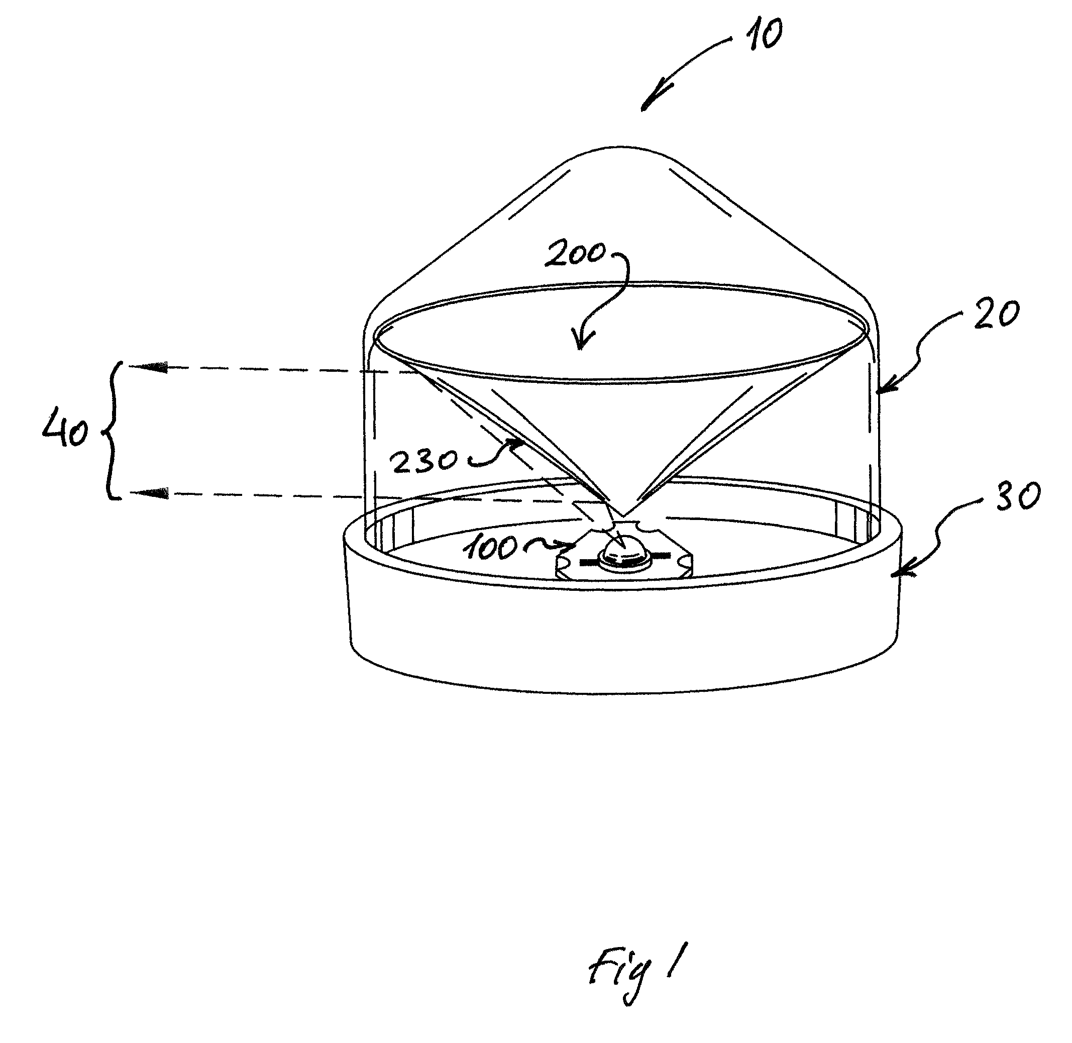
[0022]FIG. 1 is a perspective view of a light module for the omnidirectional luminaire 10. The light module 10 may comprise one or more LEDs 100 and a reflective light transformer 200. The light module 10 also can include an optical omnidirectional window 20 and a LED heat sink 30.

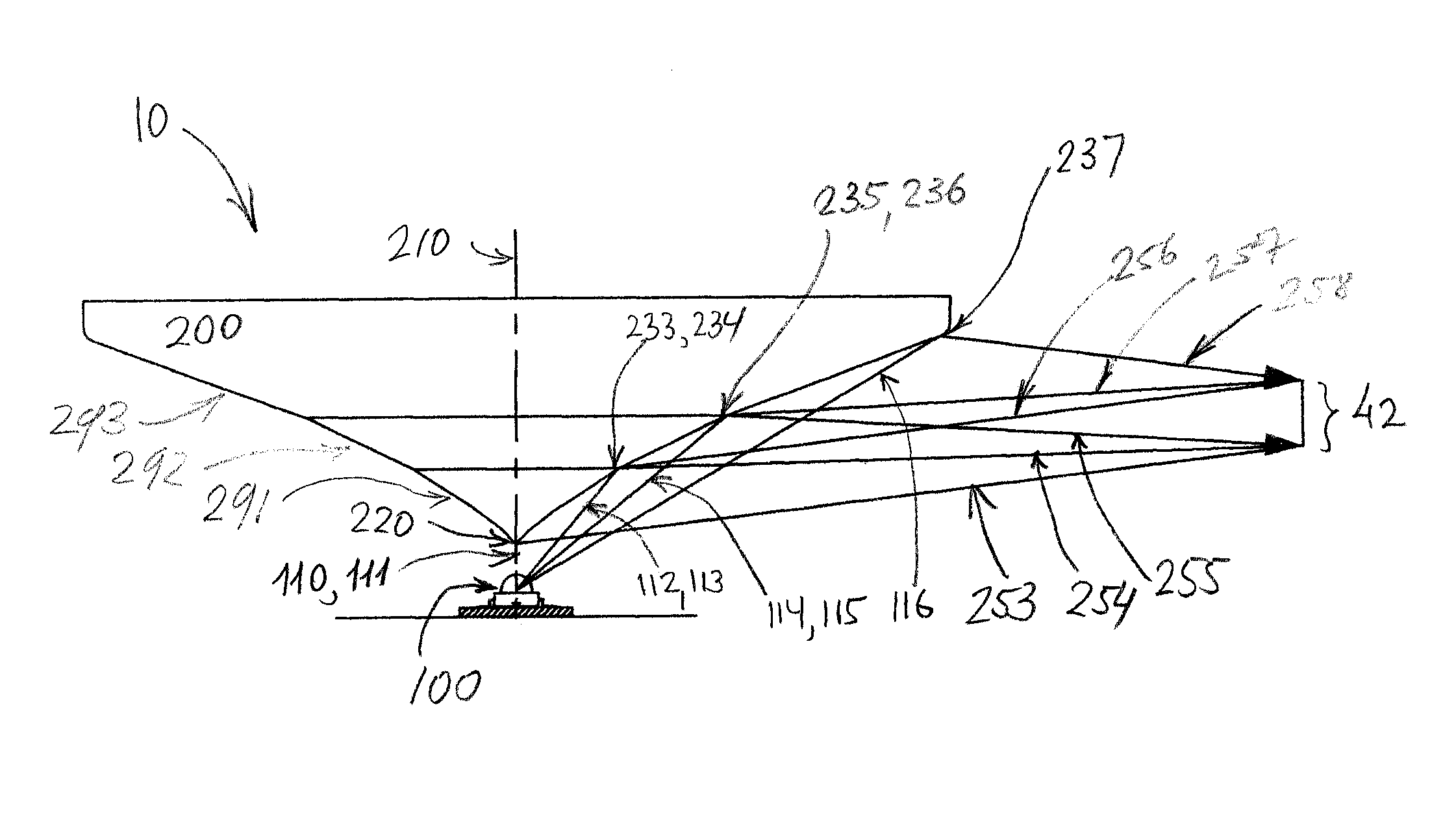
[0023]In operation, the light emitted by the LED 100 with given spatial intensity distribution is reflected by the reflective light transformer surface 230, transformed and directed omnidirectionally in 360° pattern 40, with a pre-calculated intensity distribution. In order to achieve high efficiency (80% and higher) the light transformer should be designed to take into account both the specifics of the light sources (such as the LED spatial intensity distribution) and the desirable light distribution across the emitted pattern.

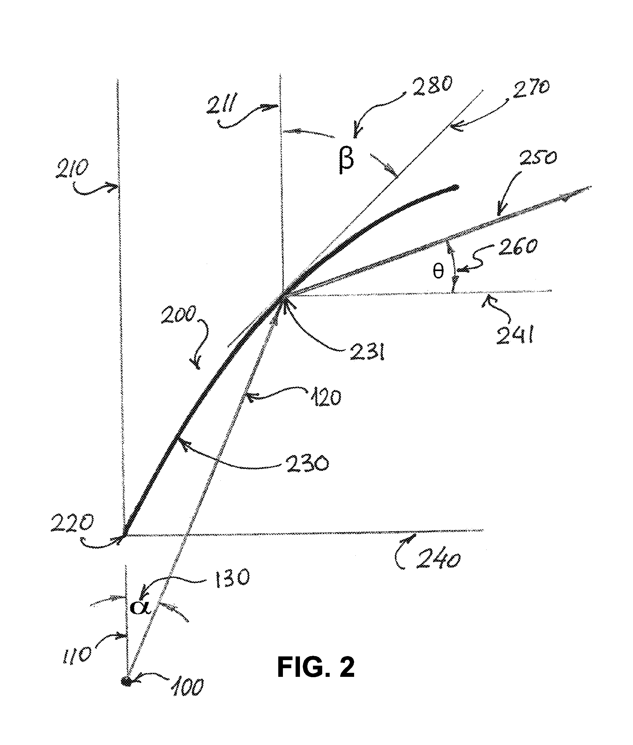
[0024]The method of reflective light transformer surface profile design using light source spatial intensity distribution and required intensity distribution across the emitted patt...


PUM


Abstract

A light module including a single light emitting diode (LED) and a rotationally symmetrical reflective light transformer providing an omnidirectional pattern with a pre-calculated intensity distribution. In alternative embodiments the light module may consist of a plurality of LEDs and the reflective light transformer, having plurality of identical segments, provides an omnidirectional pattern with a pre-calculated intensity distribution as a result of superposition of the limited angle pattern reflected by each segment. In order to provide high efficiency the light transformer reflective surface profile is designed using a given LED's spatial intensity distribution and required intensity distribution across the emitted omnidirectional pattern as a design parameters.

Description

CROSS-REFERENCE TO RELATED APPLICATION[0001]This application is a continuation-in-part of and claims priority to U.S. patent application Ser. No. 10 / 277,230, filed Oct. 21, 2002 now U.S. Pat. No. 7,503,669; which is a continuation-in-part of U.S. patent application Ser. No. 09 / 566,521, filed May 8, 2000, now U.S. Pat. No. 6,543,911 and is herein incorporated by reference.BACKGROUND OF THE INVENTION[0002]1. Field of Invention[0003]The present invention relates generally to light sources utilizing light emitting diodes (LEDs). In particular, the present invention relates to aviation signal lights providing omnidirectional patterns, such as a runway edge light, obstruction light and similar, where requirements for specific light distribution across the pattern are mandatory.[0004]2. Discussion of Relevant Prior Art[0005]Signal lights such as airfield lights and aviation obstruction lights require certification by the government (Federal Aviation Authority) or international organization...

Claims


Application Information

Patent Timeline
Patent Type & Authority Patents(United States)
IPC IPC(8): F21V7/04F21V7/10
CPCB64F1/20E01F9/065F21V7/0008F21V7/0091F21V7/04F21V21/0824F21V7/0058F21Y2103/022F21Y2101/02F21Y2103/003B64D2203/00F21V7/048F21W2111/06E01F9/559F21Y2103/10F21Y2115/10F21Y2103/33
Inventor RIZKIN, ALEXANDERTUDHOPE, ROBERT H.
Owner FARLIGHT
Why Eureka
Try Eureka