Connector banks arranged in parallel and floating manner

Active Publication Date: 2013-01-29
HUBERSUHNER AG
View PDF8 Cites 13 Cited by
  • Summary
  • Abstract
  • Description
  • Claims
  • Application Information

AI Technical Summary

Benefits of technology

[0034]A further field of application is in the “automated test equipment” market with the so-called “test heads” required there. In this case, many serial connections are routed from a so-called “load board” of a test head to a measuring station. A typical example is an existing digital IC such as a processor, graphics chip or similar components which contain a large number of serial channels and typically achieve data rates up to 6 Gbps at the present time. Data rates of up to 15 Gbps are expected in the future. The number of channels can reach 100 or more per chip. A high-quality multichannel connector with a corresponding number of channels is required for this purpose. 100 channels per square inch is advantageous on account o

Problems solved by technology

Therefore, they are suitable for transmitting high frequencies only to a limited extent.
However, these multipole plug connectors are not coaxial plug connectors in which there is always a contact pair comprising an inner contact/coaxial outer contact.
The plug connectors known from the prior art are not suitable for use in an array with a high packing density in the region of 100 channels per square inch, as are used, for example, in test arrangements for testing chips or microprocessors where a large number of connector points have to be simultaneously connected in a narrow space and high frequencies have to be transmitted.
One reason for this is that, on account of the design, an arrangement with a corresponding packing density is not possible.
It is likewise not possible to guarantee that all the connectors are reliably operatively connected to one another.
Although the described principle of a mu

Method used


Image

  • Connector banks arranged in parallel and floating manner
  • Connector banks arranged in parallel and floating manner
  • Connector banks arranged in parallel and floating manner

Examples


first embodiment

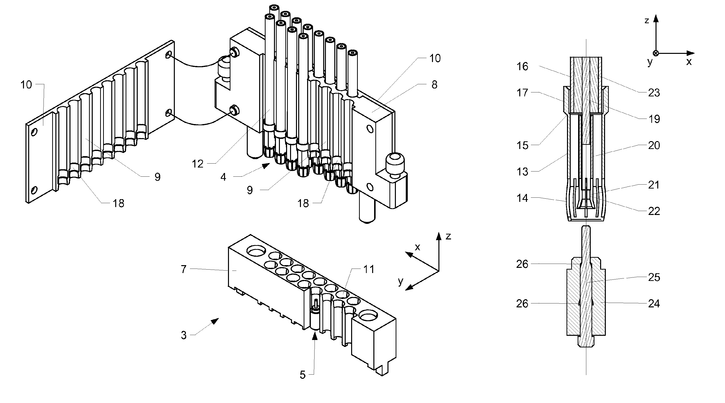
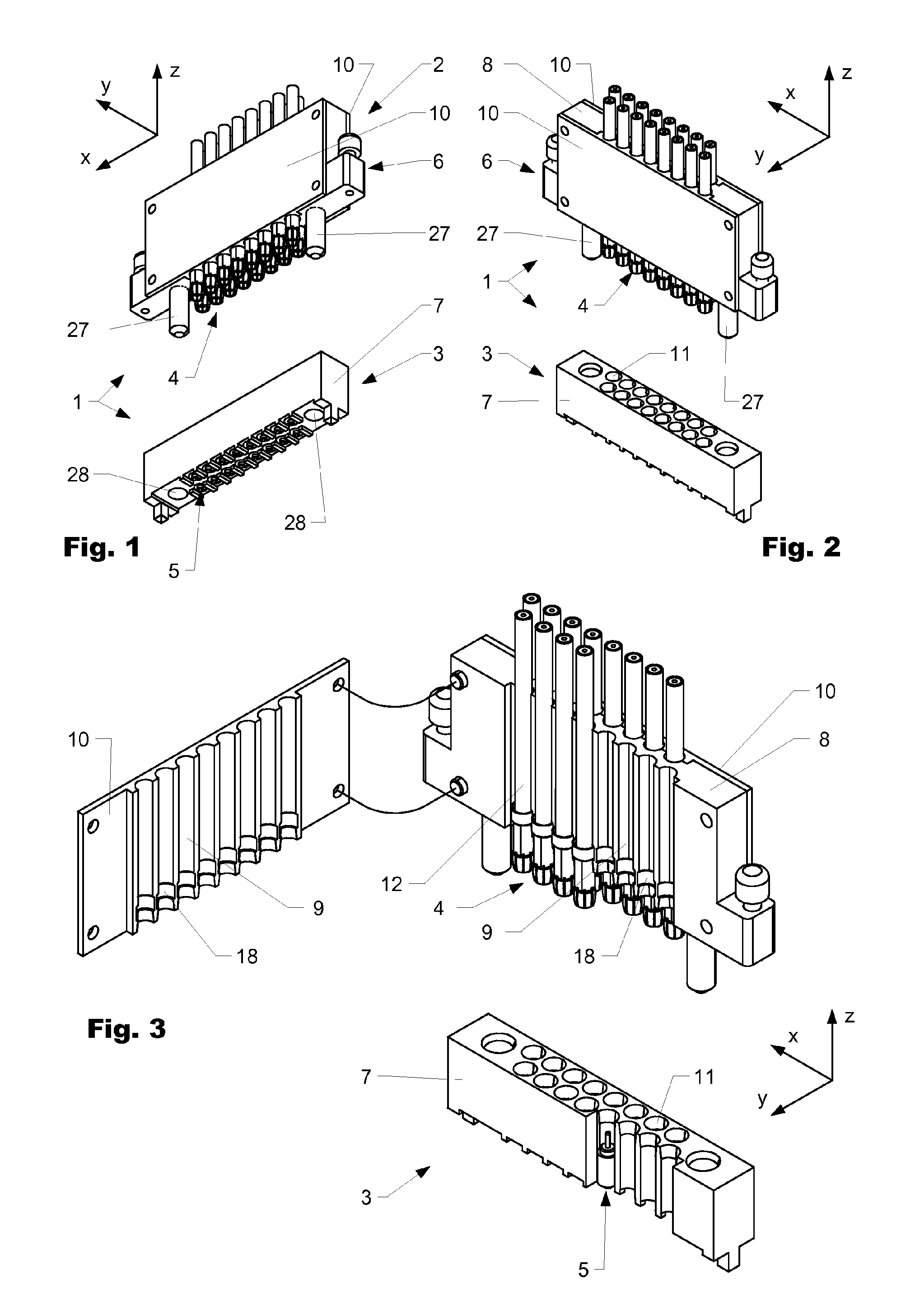
[0047]FIG. 1 shows a perspective illustration of a multiple coaxial connector 1 obliquely from the front and below. FIG. 2 shows the same multiple connector 1 obliquely from the front and above, and FIG. 3 shows an open and partially sectioned illustration of the multiple connector obliquely from above.

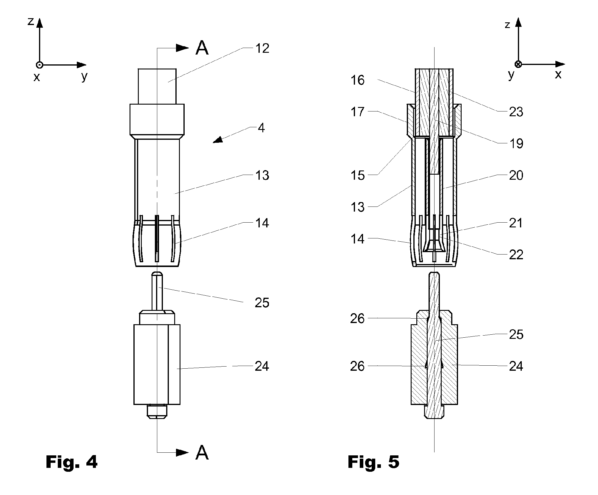
[0048]The multiple coaxial connector 1 comprises a male and a female connector bank 2, 3, which connector banks can be operatively connected to one another by a plug-connection process. The two parts 2, 3 have a plurality of male and female, here coaxial, connectors 4, 5 which are arranged in a common upper first and second lower, one- or multi-piece external housing 6, 7. The male and female coaxial connectors 4, 5 are illustrated on an enlarged scale in FIGS. 4 and 5. In the figures, the male and the female connectors 4, 5 and, respectively, the connector banks 2, 3 are illustrated in a state in which they are separated from one another (not operatively connected), so that the indiv...

second embodiment

[0063]FIG. 7 shows a perspective illustration of a multiple coaxial connector 1 obliquely from above. The construction corresponds substantially to that of the connector 1 according to FIGS. 1 to 3. Therefore, reference is made to these figures for the description of the general manner of operation. For improved understanding, the first housing 6 is illustrated in the open state and the second housing 7 is illustrated partially in section.

[0064]In contrast to the connector according to FIGS. 1 to 3, the connector shown here is of one-row design. The housing 6 of the male connector bank 2 is of two-piece design and comprises a base body 8 which has a plurality of cutouts 9, which are arranged alongside one another, for receiving cables 12 and male coaxial connectors 4 which are operatively connected to said cables. The connectors 4 have thickened portions 17 which, in the mounted state, are arranged in grooves 18 provided for them and prevent movement in the longitudinal direction. A...

third embodiment

[0065]FIG. 8 shows a perspective illustration of two male and two female connectors 4, 5, in each case one above the other. In the front connector pair 4, 5, a front region of 90° is cut away, so that the interior of the connectors 4, 5 is more clearly visible. The connectors 4, 5 correspond to the connectors 4, 5 of the multiple coaxial connector 1 according to FIG. 7 but can, in principle, also be used in an embodiment which is shown in one of the preceding figures.

[0066]The male connectors 4 have, in the interior, a first spacer sleeve 34 which is arranged between the sleeve-like outer part 13 and the first inner part 20 which is connected to the inner conductor 19 of the coaxial cable 12 and which spaces said sleeve-like outer part and first inner part apart from one other. The spacer sleeve 34 is generally produced from an insulating material and serves to hold the parts.

[0067]In this case (in contrast to the embodiment according to FIGS. 4 and 5), the female connector 5 has an...


PUM


Abstract

The present disclosure relates to a multiple coaxial connector (30) having a female connector part and a cable-side male connector part (31,33). The male connector part (31) comprises at least one single-row or double-row connector bank (2) having a housing (6), which has a base body (8) having openings (9) accessible from one or two sides, which are used for receiving individual connectors (4,5).

Description

CROSS REFERENCE TO RELATED APPLICATIONS[0001]The present application is a 35 U.S.C. §371 National Phase conversion of PCT / EP2009 / 051602, filed Feb. 11, 2009, which claims benefit of Swiss Application No. 00544 / 08, filed Apr. 8, 2008, the disclosure of which is incorporated herein by reference. The PCT International Application was published in the German language.BACKGROUND[0002]1. Field of the Disclosure[0003]The invention is found in the field of multiple coaxial connectors according to the preamble of the independent patent claim.[0004]2. Related Art[0005]The prior art discloses multiple coaxial connectors which are suitable for simultaneously connecting a plurality of connectors to a coaxial cable guide. By way of example, the applicant discloses a 16-pin multiple coaxial connector with the product designation Mc16. This connector has a spacing of around 4 mm between the individual connectors and is suitable for frequencies of up to approximately 40 GHz. Likewise known is a sing...

Claims


Application Information

Patent Timeline
IPC IPC(8): H01R13/514
CPCH01R13/514H01R24/50H01R13/518H01R2103/00
Inventor SCHWARZ, VOLKER
Owner HUBERSUHNER AG
Why Eureka
Try Eureka