
Liquid crystal display device and driving method thereof

a technology of liquid crystal display and driving method, which is applied in the direction of instruments, television systems, computing, etc., can solve the problems of insufficient viewing angle, insufficient wide angle viewing, and inability to solve the problem of lcd device technology, so as to improve the property of image display, enhance the compensating ability of color difference, and mitigate the effect of color shi

Active Publication Date: 2013-01-29
INNOLUX CORP
View PDF13 Cites 12 Cited by
  • Summary
  • Abstract
  • Description
  • Claims
  • Application Information

AI Technical Summary

Benefits of technology

[0015]In view of the foregoing, embodiments of the invention disclosed herein provide an LCD device and a driving method thereof, which can improve the γ property of image displaying and further enhance color difference compensation.
[0021]As mentioned above, each pixel includes a first sub-pixel and a second sub-pixel in the LCD device of the invention, and the capacitance ratio of the liquid crystal capacitor to the storage capacitor in the first sub-pixel is smaller than that of the liquid crystal capacitor to the storage capacitor in the second sub-pixel. Therefore, the LCD device and the driving method thereof according to the invention can make the γ value of the LCD device approach the ideal value, effectively improve the γ property of image displaying, and thus enhance the color difference compensating ability. Thus, mitigating the effects of the phenomenon of color shift can be improved, and better image display quality can be obtained.

Problems solved by technology

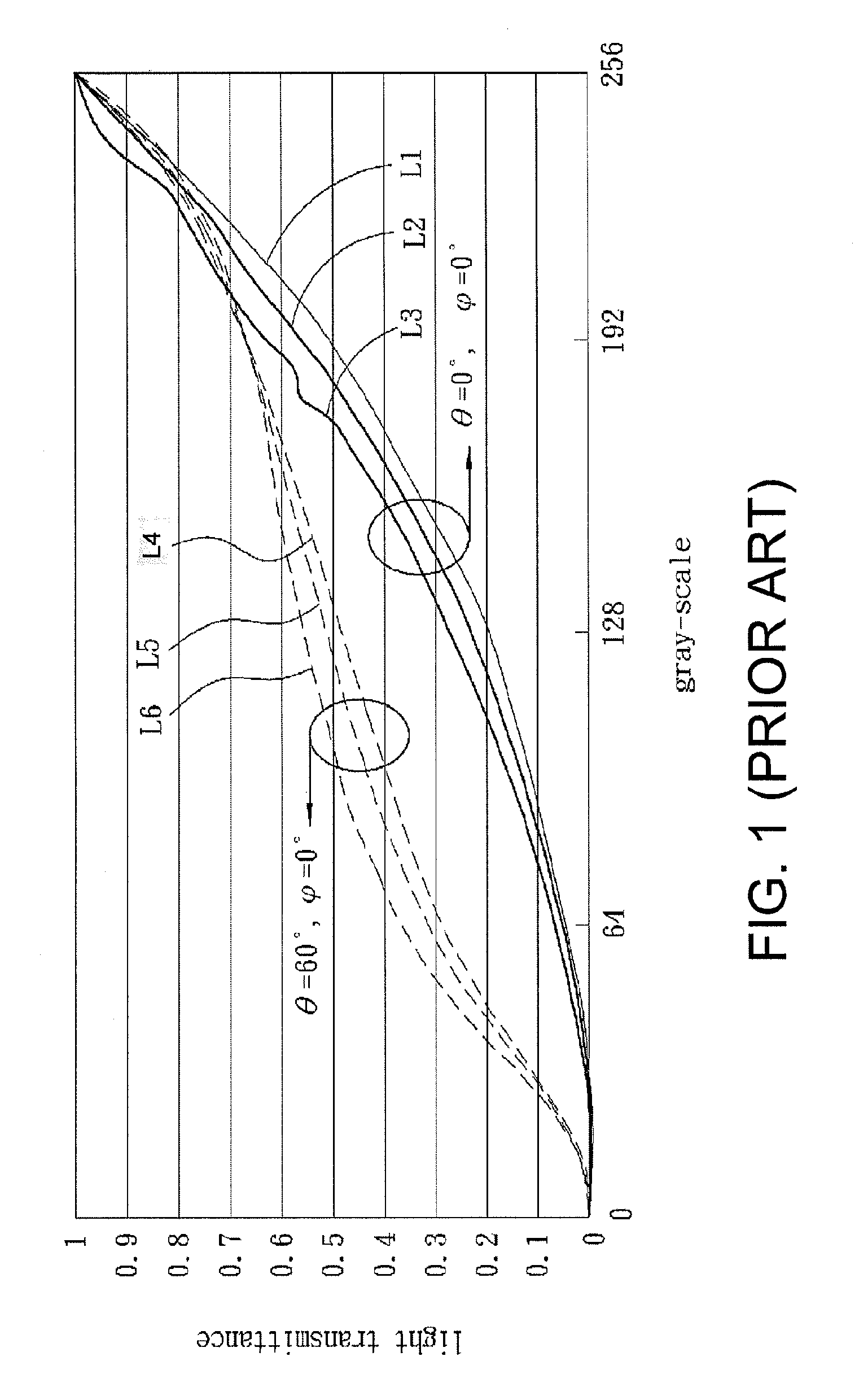
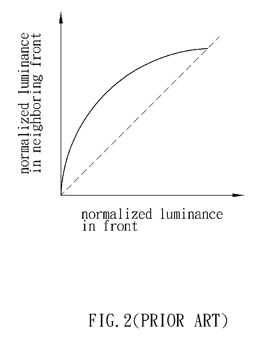
However, the LCD device still has some technological problems to be solved, such as the problem of wide angle viewing.
In practice, however, the LCD device has the problem that the viewing angle is not wide enough.
In addition, because the highest voltage value is usually fixed, it cannot be changed by adjusting the input signal, so the overall luminance of the display may deteriorate.

Method used


Image

  • Liquid crystal display device and driving method thereof
  • Liquid crystal display device and driving method thereof
  • Liquid crystal display device and driving method thereof

Examples


first embodiment

[0047]FIG. 9 is an overall schematic illustration depicting a multi-domain LCD device 2 according to a first embodiment of the invention. Referring to FIG. 9, the multi-domain LCD device 2 includes a liquid crystal panel 200, a source driver 202 and a gate driver 204. The liquid crystal panel 200 includes n×m pixels 20. The source driver 202 transfers display data to the pixels 20 through data lines D(1) to D(n). The gate driver 204 transfers scan signals to the liquid crystal panel 200 through scan lines S(1) to S(m) to sequentially turn on each column of pixels 20, and transfers a first bias signal and a second bias signal to each of the pixels 20 on the liquid crystal panel 200 through first storage capacitor lines B1(1) to B1(m) and second storage capacitor lines B2(1) to B2(m). The data lines D(1) to D(n) are formed on the liquid crystal panel 200 along a first direction and provide an input voltage. The scan lines S(1) to S(m) are formed on the liquid crystal panel 200 along a...

second embodiment

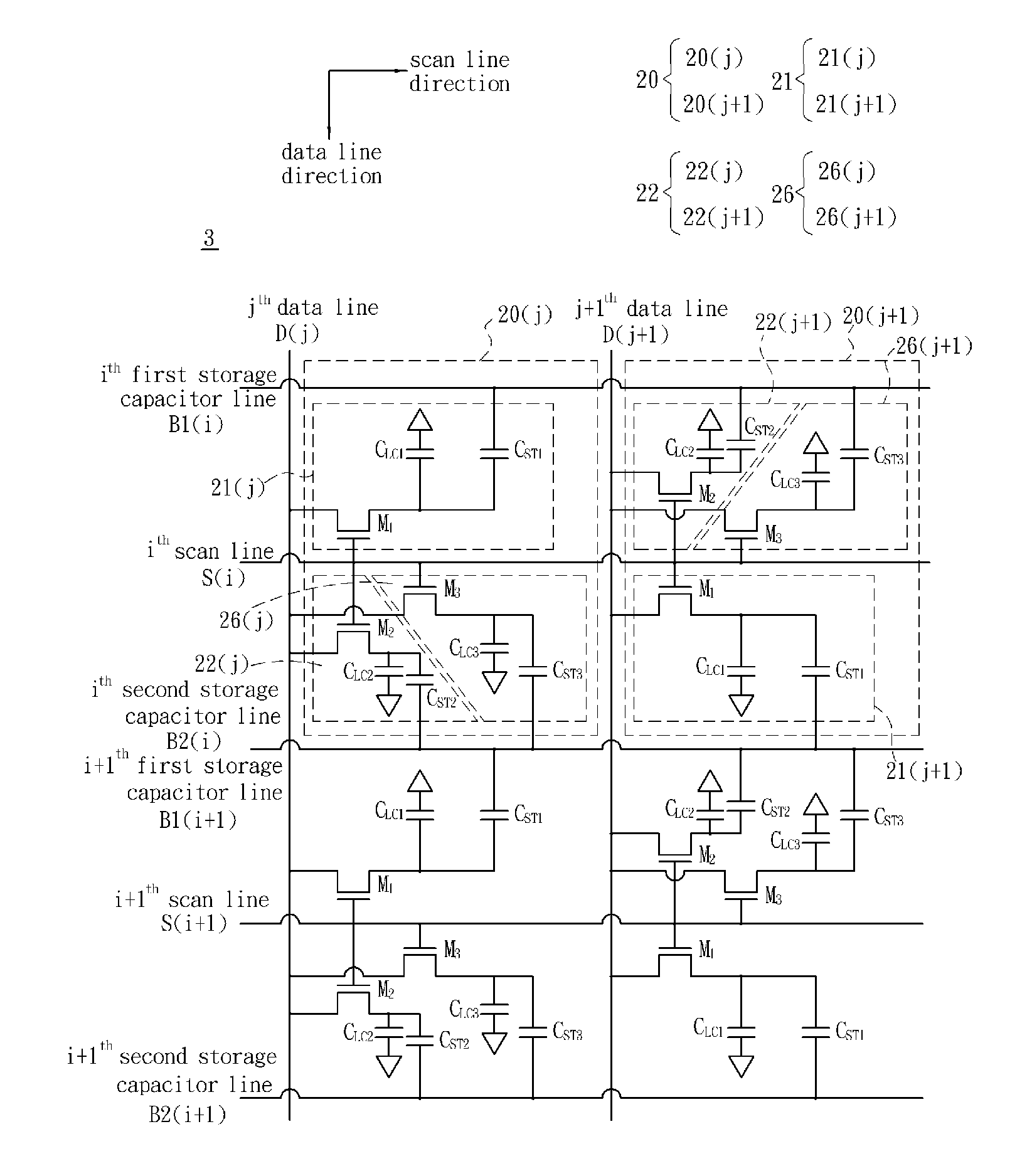
[0074]FIG. 15 depicts a multi-domain LCD device 3 according to a second embodiment of the invention. In this embodiment, each pixel 20 further includes a third sub-pixel 26, which includes a liquid crystal capacitor CLC3, a storage capacitor CST3 and a switch element M3. In addition, a capacitance ratio of the storage capacitor CST2 to the liquid crystal capacitor CLC2 in the second sub-pixel 22 is smaller than that of the storage capacitor CST3 to the liquid crystal capacitor CLC3 in the third sub-pixel 26 (CST2 / CLC2ST3 / CLC3) in this embodiment. Also, in the neighboring two pixels 20(j) and 20(j+1) of this embodiment, the third sub-pixel 26(j) of the pixel 20(j) and the third sub-pixel 26(j+1) of the neighboring next pixel 20(j+1) are staggered. In the neighboring two pixels 20(j) and 20(j+1) disposed along the scan line direction according to this embodiment, the first sub-pixel 21(j), the second sub-pixel 22(j) and the third sub-pixel 26(j) of the pixel 20(j) and the first sub-pi...

third embodiment

[0080]Non-limiting, one pixel may be divided into four or more than four sub-pixels in the disclosed LCD device, and the implementing method thereof may be derived by one of ordinary skill in the art according to the above-mentioned embodiments. The embodiment, in which one pixel is divided into four sub-pixels, is illustrated.

[0081]FIG. 18 depicts LCD device 4. In this embodiment, each pixel 20 includes a first sub-pixel 21, a second sub-pixel 22, a third sub-pixel 26, and a fourth sub-pixel 27. For example, the pixel 20(j) includes a first sub-pixel 21(j), a second sub-pixel 22(j), a third sub-pixel 26(j) and a fourth sub-pixel 27(j), the pixel 20(j+1) includes a first sub-pixel 21(j+1), a second sub-pixel 22(j+1), a third sub-pixel 26(j+1) and a fourth sub-pixel 27(j+1), and so on. The first sub-pixels 21(j) and 21(j+1) and the second sub-pixels 22(j) and 22(j+1) are in charge of displaying the darker signal, and the third sub-pixels 26(j) and 26(j+1) and the fourth sub-pixels 27...


PUM


Abstract

An LCD device includes a plurality of pixels arranged in a matrix. Each pixel includes a first sub-pixel and a second sub-pixel. Each of the first and second sub-pixels includes a liquid crystal capacitor and a storage capacitor. A capacitance ratio of the liquid crystal capacitor to the storage capacitor in the first sub-pixel is smaller than that in the second sub-pixel. In a first pixel and a second pixel among all the pixels, the first sub-pixel of the first pixel and the first sub-pixel of the second pixel are staggered, and the second sub-pixel of the first pixel and the second sub-pixel of the second pixel are staggered.

Description

RELATED APPLICATIONS[0001]The present application is based on, and claims priority from, Taiwan Application Number 95145794, filed Dec. 7, 2006, the disclosure of which is hereby incorporated by reference herein in its entirety.BACKGROUND OF THE INVENTION[0002]1. Field of Invention[0003]The invention relates to a liquid crystal display (LCD) device and, in particular, to a pixel arrangement and a driving method of an LCD device.[0004]2. Related Art[0005]An LCD device is one type of usually flat panel displays and has the advantages of high resolution, light weight, a thin thickness, and low power consumption. Thus, LCD devices, which are more and more widely, used serve as computer display devices and touch screens for man-machine interfaces, and are also combined with video systems to form televisions.[0006]However, the LCD device still has some technological problems to be solved, such as the problem of wide angle viewing. The viewing angle of the LCD device relates to the γ prope...

Claims


Application Information

Patent Timeline
Patent Type & Authority Patents(United States)
IPC IPC(8): G09G3/38
CPCG02F1/136213G09G3/3648G02F1/133707G02F2001/134345G09G2300/0876G09G2310/0205G09G2320/028G02F1/134345
Inventor HSIEH, CHIH-YUNGHSIEH, MING-FENGHSU, CHE-MING
Owner INNOLUX CORP
Learn More