
Method and apparatus for estimating sound source

a sound source and method technology, applied in the direction of direction finders, instruments, measurement devices, etc., can solve the problems of inability to verify the validity of the measurement taken, inability to see, and considerable time taken for the analysis so as to achieve efficient and effective use, and efficient estimation of the sound source position

Active Publication Date: 2013-01-29
HONDA MOTOR CO LTD
View PDF12 Cites 0 Cited by
  • Summary
  • Abstract
  • Description
  • Claims
  • Application Information

AI Technical Summary

Benefits of technology

This patent is about a method for estimating the position of a sound source by using microphones to sample the sound and image simultaneously. The sound pressure waveform data and image data are stored in a storage means, and then the sound pressure waveform data is called up and a graph of its time-series waveform is displayed. The temporal position of the sound source is designated on the graph and its direction is estimated using the sound pressure waveform data for a predetermined calculation time length. This method allows for the efficient and accurate estimation of the horizontal and elevation angles of the sound source position with a smaller number of microphones.

Problems solved by technology

As a result, the analysis of the sound source position takes a considerable time, and it is not possible to see the result of the sound source estimation instantly on the spot.
Also, another drawback of the method is its inability to verify the validity of the measurement taken.

Method used


Image

  • Method and apparatus for estimating sound source
  • Method and apparatus for estimating sound source
  • Method and apparatus for estimating sound source

Examples


first embodiment

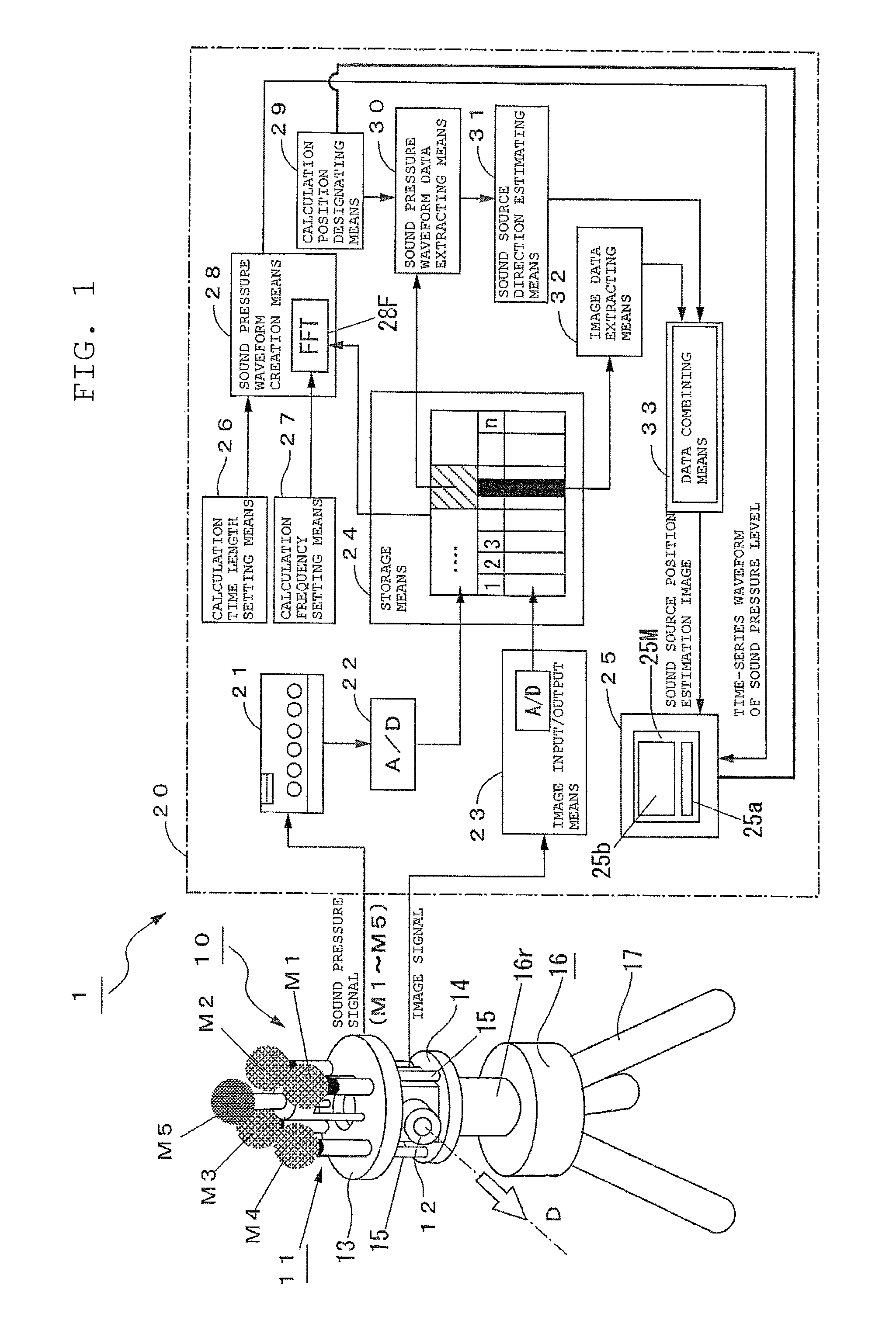
[0049]FIG. 1 is a functional block diagram showing a structure of a sound source estimation system 1 according to a first embodiment of the present invention. The sound source estimation system 1 includes a sound / image sampling unit 10 and a sound source position estimating unit 20. The sound / image sampling unit 10 includes a sound sampling means 11, a CCD camera (hereinafter referred to as “camera”) 12, which is an image sampling means, a microphone fixture 13, a camera support base 14, props 15, a swivel base 16, and a pedestal 17. The sound sampling means 11 includes a plurality of microphones M1 to M5.

[0050]The microphones M1 to M5 are installed on the microphone fixture 13, and the camera 12 is installed on the camera support base 14. The microphone fixture 13 and the camera support base 14 are joined to each other with three props 15. In other words, the sound sampling means 11 and the camera 12 are integrally structured together. Note also that the microphones M1 to M5 are lo...

second embodiment

[0096]A second embodiment of the present invention provides a reinforcement of the first embodiment in better coping with situations where sudden sounds or intermittent sounds are expected.

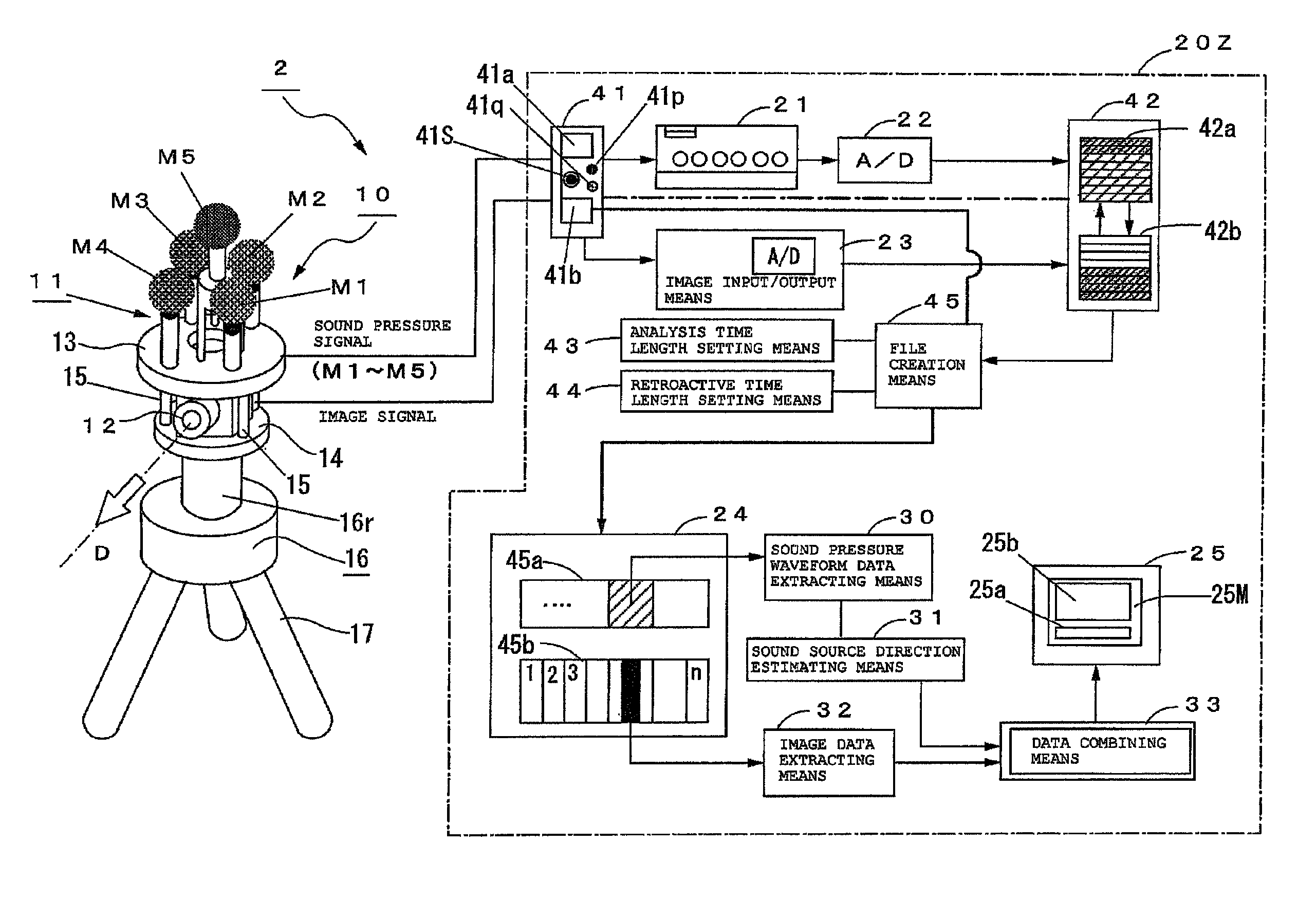
[0097]As shown in FIG. 5, a sound source estimation system 2 according to the second embodiment is provided with a means of temporarily storing sound pressure signals, which are A / D converted by an A / D converter 22, and image signals, which are A / D converted by an image input / output means 23, as sound waveform data and image data, respectively, and a means of outputting a command signal to start the estimation of sound direction (measurement start signal output unit 41a of mode switching means 41). And the system extracts sound pressure waveform data and image data from a time point a predetermined retroactive time length before the issue of a command to start a sound direction measurement to a time point a predetermined analysis time length thereafter, when such a command is issued, and estimates...


PUM


Abstract

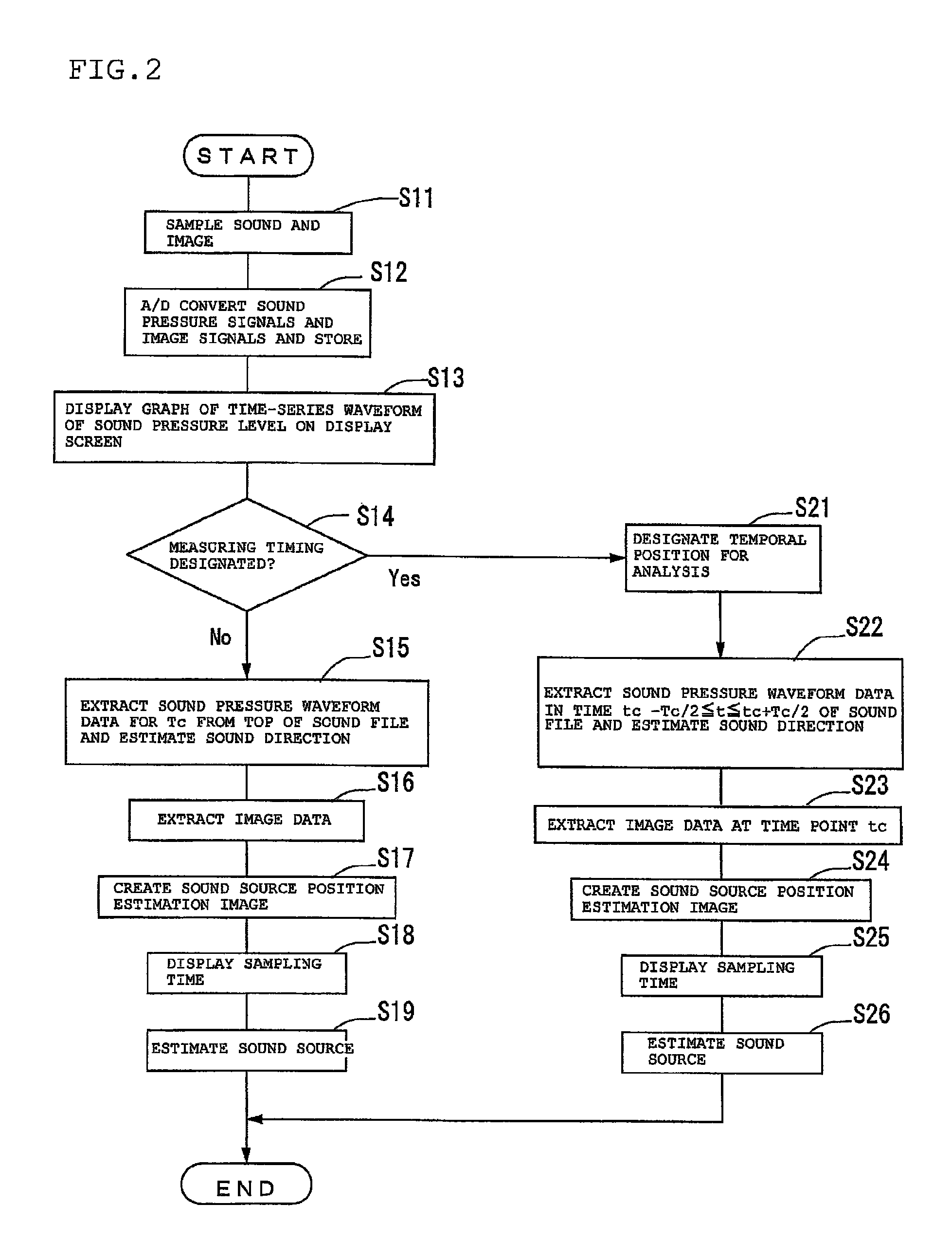
Sound and image are sampled simultaneously using a sound / image sampling unit incorporating a plurality of microphones and a camera. Sound pressure waveform data and image data are stored in a storage means. Then the sound pressure waveform data are extracted from the storage means, and a graph of a time-series waveform of the sound pressure level is displayed on a display screen. A time point at which to carry out a calculation to estimate sound direction is designated on the graph, and then sound direction is estimated by calculating the phase differences between the sound pressure signals of the sound sampled by the microphones, using the sound pressure waveform data for a calculation time length having the time point at the center thereof. A sound source position estimation image having a graphic indicating an estimated sound direction is created and displayed by combining the estimated sound direction and the image data sampled at the time point.

Description

FIELD OF THE INVENTION[0001]The present invention relates to a method and an apparatus for estimating a sound source using sound information sampled by a plurality of microphones and image information sampled by an image pickup means.BACKGROUND OF THE INVENTION[0002]There is an acoustic technique among conventional methods for estimating the direction-of-arrival (DOA) of a sound (or sounds). In this technique, an array of microphones is set up at equally-spaced intervals, and the direction of a sound source, or the direction-of-arrival of a sound wave, is estimated from the phase differences of microphones with respect to a reference microphone. An example of such a technique is disclosed in the book entitled “Acoustic System and Digital Processing” by Juro Ohga, Yoshio Yamazaki, and Noboru Kaneda, Corona Publishing Co., 1995, the disclosure being hereby incorporated herein by reference.[0003]There is, on the other hand, another method for estimating the direction of a sound source ...

Claims


Application Information

Patent Timeline
Patent Type & Authority Patents(United States)
IPC IPC(8): G01S3/80
CPCG01S3/8083
Inventor OWAKI, MASANAOZAIMA, TAKEFUMIMASE, KOJI
Owner HONDA MOTOR CO LTD
Learn More