Fin-shaped heater stack and method for formation

a heater stack and fin-shaped technology, applied in printing and other directions, can solve the problems of dramatic decrease, thermal limitation of printing heads that try to achieve this goal, and reducing fire frequency

Active Publication Date: 2013-02-05
FUNAI ELECTRIC CO LTD
View PDF4 Cites 0 Cited by
  • Summary
  • Abstract
  • Description
  • Claims
  • Application Information

AI Technical Summary

Benefits of technology

[0008]Various embodiments of the present invention address some or all of the foregoing needs by providing an innovation that moves from a substantially planar heater stack to a vertical fin-shaped heater stack. (A definition of fin-shaped as used herein is having the shape of a projecting, approximately flat, plate or structure.) This eliminates the heater dimension as a constraint factor enabling a high density heater array, greatly reduces the water hammer effect during ink refill, and greatly reduces cavitation force due to bubble collapse. In some embodiments, water hammer and cavitation forces on the heater stack surface are reduced due to the fact that the heater stack surface is disposed parallel to ink flow and jetting direction. All of these will result in significantly increased heater stack reliability. With the vertical fin-shaped heater stack, the area of underlying silicon substrate is also reduced and ink bubbles can form on both sides of the heater stack with minimum thermal loss to the surrounding substrate, which results in marked improvement of ejector efficiency.
[0009]Accordingly, in an aspect of the present invention, a fin-shaped heater stack includes first strata configured to support and form fluid heater elements responsive to repetitive electrical activation and deactivation to produce repetitive cycles of ejection of a fluid, and second strata on the first strata to protect the fluid heater elements from adverse effects of the repetitive cycles of fluid ejection and of contact with the fluid. The first strata includes a substrate having a front surface, and a heater substrata supported on the front surface having a pair of opposite facing side surfaces extending approximately perpendicular to the front surface and an end surface interconnecting the side surfaces extending approximately parallel to the front surface such that the heater substrata is provided in a fin-shaped configuration on the substrate with the fluid heater elements forming the opposite facing side surfaces of the heater substrata.
[0010]In another aspect of the present invention, a method for forming a fin-shaped heater stack includes processing one sequence of materials to produce a first strata having a substrate and heater substrata supported on a front surface of the substrate with a pair of side surfaces oppositely facing from one another and extending approximately perpendicular to the front surface and an end surface interconnecting the side surfaces and extending approximately parallel to the front surface such that the heater substrata is provided in a fin-shaped configuration on the substrate having fluid heater elements forming the opposite facing side surfaces and being responsive to repetitive electrical activation and deactivation to produce repetitive cycles of ejection of a fluid, and processing another sequence of materials to produce a second strata on first strata to protect the fluid heater elements from adverse effects of the repetitive cycles of fluid ejection and of contact with the fluid.

Problems solved by technology

However, given current inks, flow features and nozzle materials, ejector and circuit design, and thin film materials in the heater stack, any printhead that attempts to achieve this goal would be thermally limited due to extreme heat generated on the chip, and specially limited by heater dimension.
Conversely, reducing the fire frequency for thermal management would require such a dramatic decrease that the print speed would be extremely slow.
However, a large portion of the energy is dissipated in the materials over and under the heater.
However, most heater designs require ˜10 μm heater width, which makes it difficult to form flow features and chamber walls.
However, reliability is a huge concern for such designs, since water hammer and cavitation forces could easily damage such thin layer(s).

Method used


Image

  • Fin-shaped heater stack and method for formation
  • Fin-shaped heater stack and method for formation
  • Fin-shaped heater stack and method for formation

Examples


Embodiment Construction

[0018]The present invention now will be described more fully hereinafter with reference to the accompanying drawings, in which some, but not all embodiments of the invention are shown. Indeed, the invention may be embodied in many different forms and should not be construed as limited to the embodiments set forth herein; rather, these embodiments are provided so that this disclosure will satisfy applicable legal requirements. Like numerals refer to like elements throughout the views.

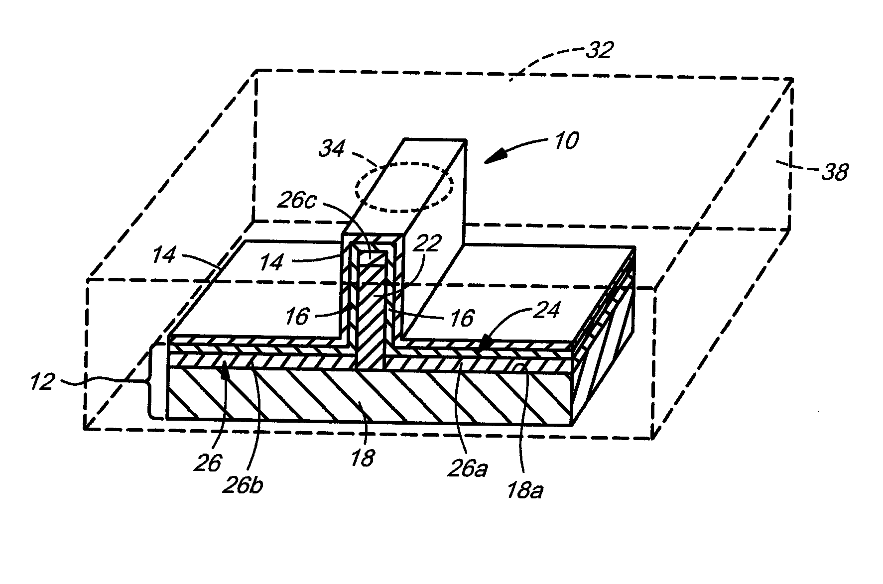
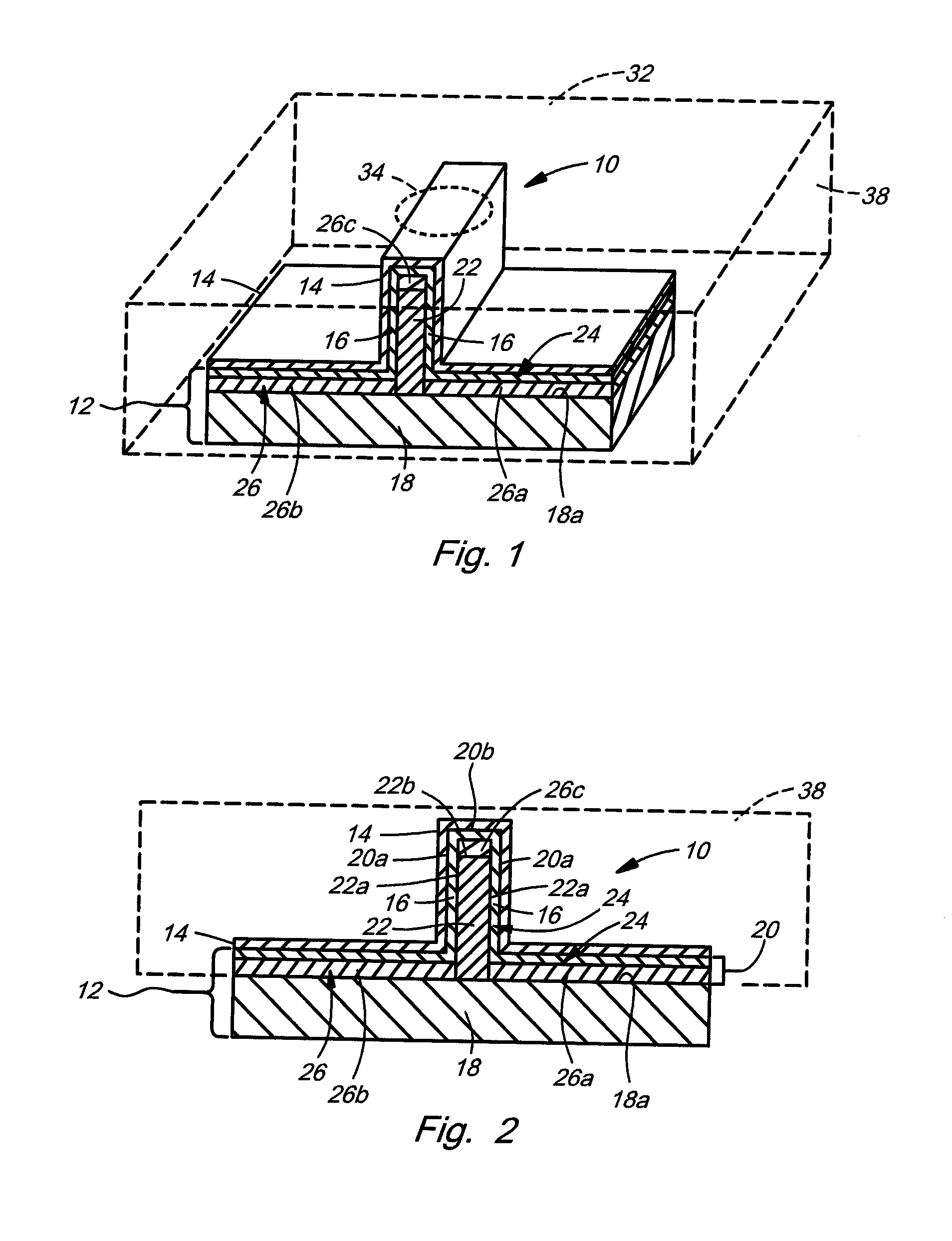
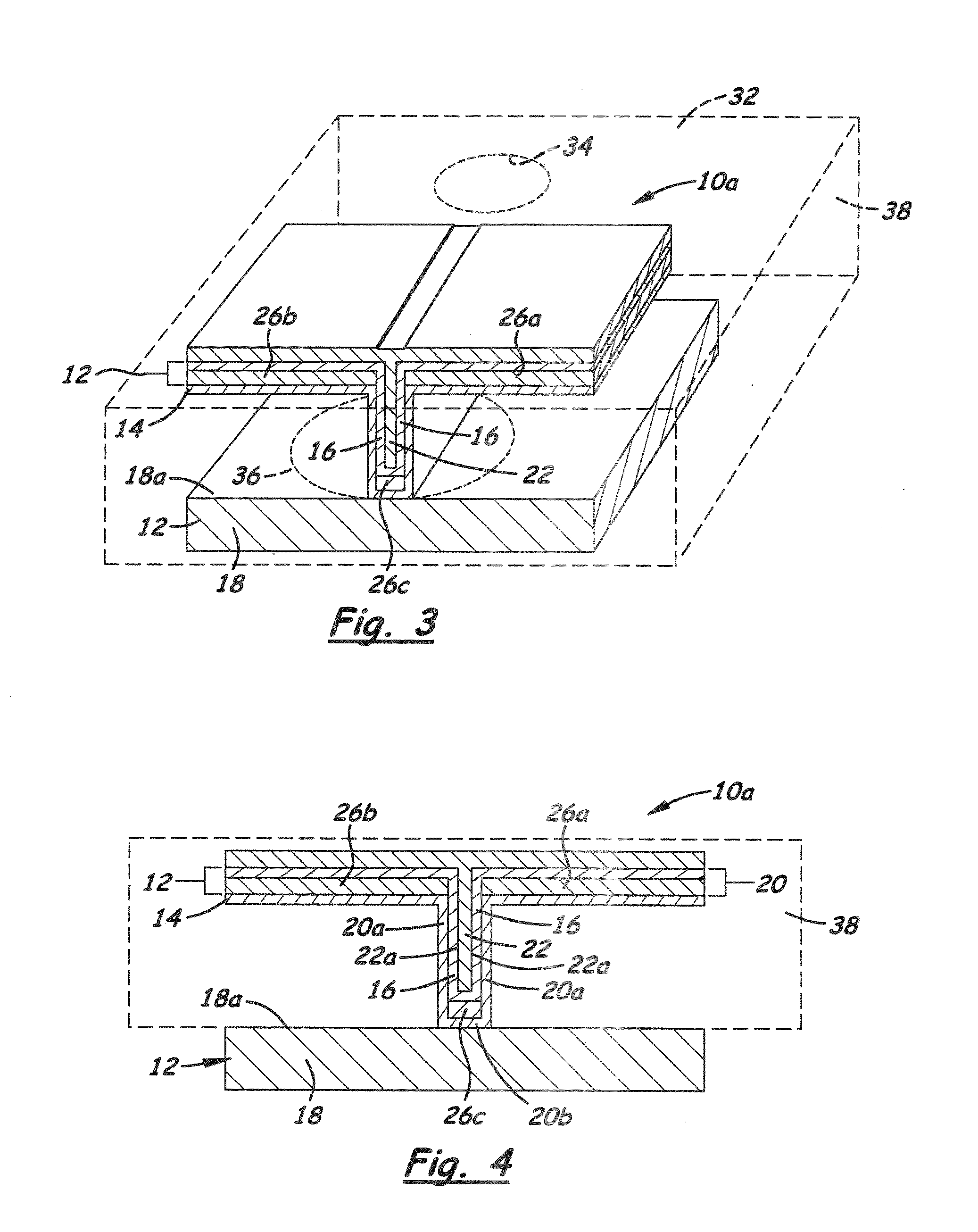
[0019]Referring now to FIGS. 1-4, there are illustrated exemplary embodiments of a vertical fin-shaped heater stack, generally designated 10 and 10a. FIGS. 1 and 2 illustrate the upright vertical configuration of the fin-shaped heater stack 10. FIGS. 3 and 4 illustrate the inverted vertical configuration of the fin-shaped heater stack 10a. Each of the upright and inverted vertical configurations of the heater stacks 10 and 10a includes first and second strata 12, 14. The first strata 12 of both heater st...


PUM

PropertyMeasurementUnit
widthaaaaaaaaaa
thicknessaaaaaaaaaa
widthaaaaaaaaaa

Abstract

A fin-shaped heater stack includes first strata configured to support and form fluid heater elements responsive to repetitive electrical activation and deactivation to produce repetitive cycles of ejection of a fluid, and second strata on the first strata to protect the fluid heater elements from adverse effects of the repetitive cycles of fluid ejection and of contact with the fluid. The first strata include a substrate having a front surface, and heater substrata supported on the front surface. The heater substrata have opposite facing side surfaces which extend approximately perpendicular to the front surface and an end surface interconnecting the side surfaces which extends approximately parallel to the front surface such that the heater substrata is provided in either an upright or inverted fin-shaped configuration on the substrate with the fluid heater elements forming the opposite facing side surfaces of the heat substrata.

Description

CROSS REFERENCES TO RELATED APPLICATIONS[0001]None.BACKGROUND[0002]1. Field of the Invention[0003]The present invention relates generally to micro-fluid ejection devices and, more particularly, to a fin-shaped heater stack and method for formation.[0004]2. Description of the Related Art[0005]The realization of ultimate inkjet print quality is influenced by several factors, of which one important driving force is the reduction of droplet size and spacing to the minimum detectable limits of the human eye. A desirable goal might be to achieve 1.5 pL drops placed at 1800 dpi. However, given current inks, flow features and nozzle materials, ejector and circuit design, and thin film materials in the heater stack, any printhead that attempts to achieve this goal would be thermally limited due to extreme heat generated on the chip, and specially limited by heater dimension. In order to maintain competitive print speeds, the chip would rapidly rise to >>100° C., eliminating drop-on-dem...

Claims


Application Information

Patent Timeline
Patent Type & Authority Patents(United States)
IPC IPC(8): B41J2/05
CPCB41J2/1412B41J2/14129B41J2/1603B41J2/1628B41J2/1642B41J2/1645B41J2/1646B41J2/1639Y10T29/49
Inventor GUAN, YIMINJOYNER, II, BURTON LEEREITMEIER, ZACHARY JUSTINSULLIVAN, CARL EDMOND
Owner FUNAI ELECTRIC CO LTD
Why Eureka
Try Eureka