Pump assembly and method

a technology of pump and assembly method, applied in the field of pumps, can solve the problems of time-consuming and labor-intensive mounting and adjustment procedure, and achieve the effect of improving the quality of the pump

Active Publication Date: 2013-02-05
XYLEM IP HLDG
View PDF6 Cites 21 Cited by
  • Summary
  • Abstract
  • Description
  • Claims
  • Application Information

AI Technical Summary

Benefits of technology

[0013]It is another object of the present invention to provide a pump assembly which is designed for ease of mounting, and by which the risk of non-proper mounting is eliminated.
[0014]Still another object is to provide a pump assembly wherein setting of an accurate axial clearance between components taking part in a shearing action does not affect, and is not affected by, the axial setting of the pump wheel.
[0016]Briefly, a pump assembly according to the present invention comprises a cutting wheel mounted on a drive shaft in coaxial and co-rotational relation with a pump wheel, and a cutting plate stationary mountable in a pump housing between the cutting wheel and the pump wheel, the cutting plate having perforations forming passages there through for a liquid to be transported by the pump wheel in rotation, the cutting wheel and cutting plate in co-operation providing a shearing interface effective for cutting solid matter that may be entrained in the liquid. The pump assembly is characterized in that the cutting wheel has an internal thread engaging an external thread on the drive shaft, the pump assembly further comprises an adjusting element, which is arranged to establish an axial clearance at the shearing interface between the cutting wheel and the cutting plate by applying a separating axial force on the cutting wheel and on the drive shaft and thereby eliminating an axial play in the threaded engagement between the cutting wheel and the drive shaft.
[0024]applying an adjusting element (22), which is arranged to establish an axial clearance at the shearing interface between the cutting wheel and the cutting plate by applying a separating axial force on the cutting wheel and on the drive shaft and thereby eliminating an axial play in the threaded engagement between the cutting wheel and the drive shaft.

Problems solved by technology

Obviously the mounting and adjustment procedure is time-wasting, and the method relying on an operator's skill to ensure a reproducible clearance at all times. But since the ability to cut down solid matter that would otherwise block the liquid intake is crucial to the chopping pump's operation, the accurate axial clearance has always to be ensured.
It is thus a technical problem to improve the prior art chopping pump such that an operative axial clearance between cutting elements is always reproduced upon mounting, and by which the risk of non-proper mounting is eliminated.

Method used


Image

  • Pump assembly and method
  • Pump assembly and method
  • Pump assembly and method

Examples


Embodiment Construction

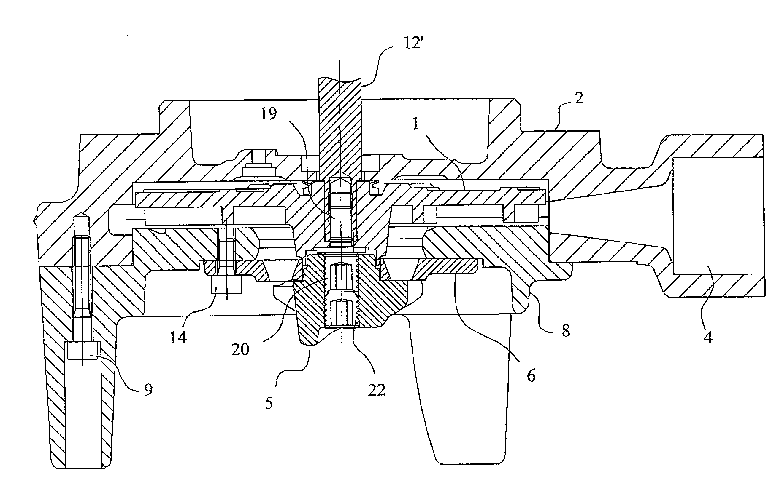
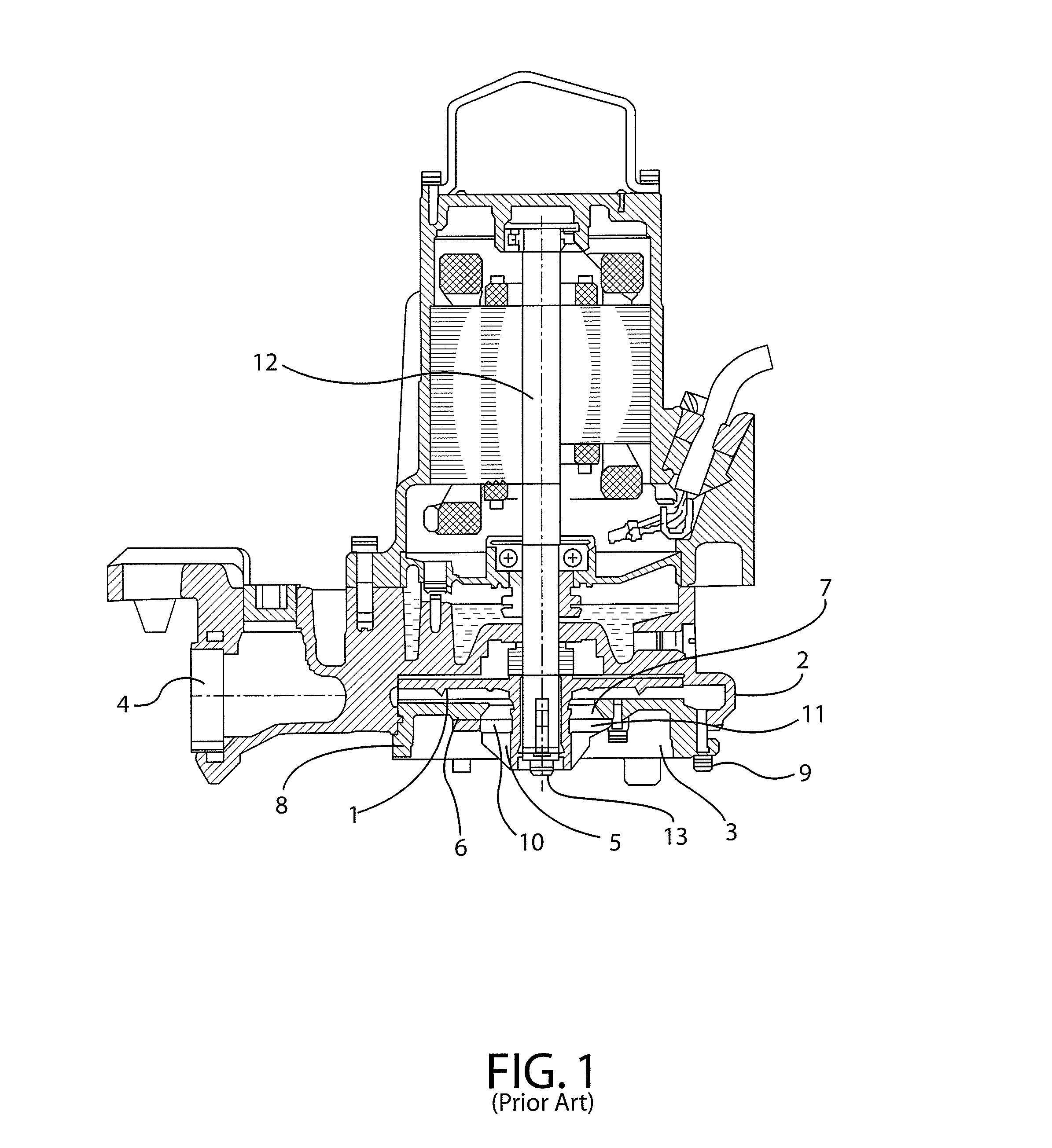
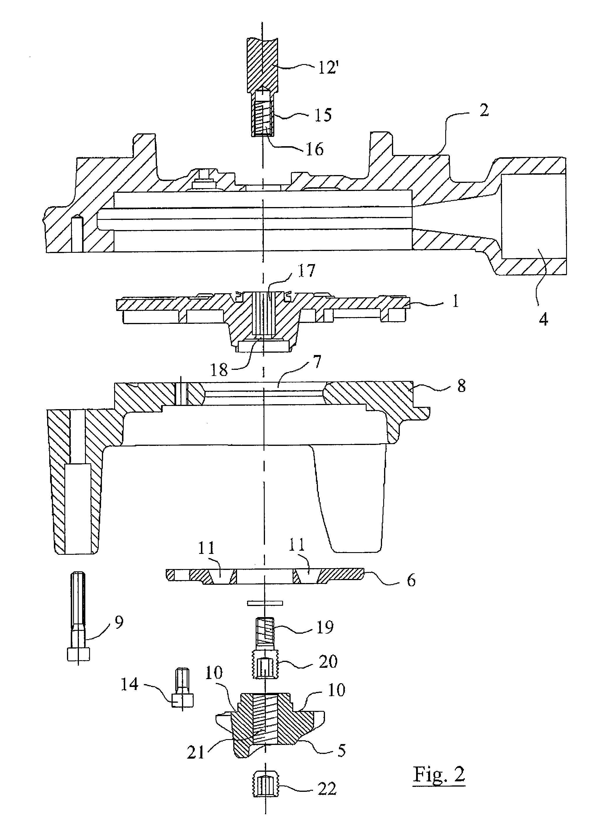
[0030]Referring initially to FIG. 1, the prior art chopping pump illustrated therein is best understood with reference to the written description given above. The invention is thus first illustrated in FIG. 2, wherein pump components are defined by the same reference numbers that are used in connection with the corresponding pump components of FIG. 1.

[0031]With reference to FIG. 2, a pump housing 2 has a chamber wherein an impeller pump wheel 1 is journalled and driven for rotation. An intake opening 7 is formed through a suction plate 8 that is stationary mountable to the pump housing by means of bolts 9. In operation, as the pump wheel rotates, liquid is sucked in through the intake opening and discharged through the radial discharge 4 by centrifugal forces generated from vanes formed on the pump wheel. The operation, which is well known, is that of a typical centrifugal pump and needs no further explanation herein.

[0032]A cutting plate 6 is stationary mountable to the suction pla...


PUM

PropertyMeasurementUnit
axial forceaaaaaaaaaa
torqueaaaaaaaaaa
pressureaaaaaaaaaa

Abstract

The invention refers to a pump assembly, and more specifically to a chopping pump assembly comprising a cutting wheel mounted on a drive shaft in coaxial and co-rotational relation with a pump wheel, and a cutting plate stationary mountable in a pump housing between the cutting wheel and the pump wheel, the cutting plate having perforations forming passages there through for a liquid to be transported by the pump wheel in rotation, the cutting wheel and cutting plate in co-operation providing a shearing interface effective for cutting solid matter which may be entrained in the liquid. An axial clearance between the cutting wheel and cutting plate is established at all times by eliminating an axial play in a threaded engagement between the cutting wheel and the drive shaft. The invention also refers to a method by which an operative shearing action is securable in the pump assembly.

Description

[0001]This application is the U.S. national phase application of PCT International No. PCT / SE2008 / 050523, filed May 7, 2008, which claims priority to Swedish Patent Application No. 0701105-9, filed May 8, 2007, the contents of such patents being incorporated by reference herein.TECHNICAL FIELD OF THE INVENTION[0002]The present invention relates to pumps and to the assembly thereof. More specifically, the invention relates to a pump assembly comprising a cutting wheel mounted in coaxial and co-rotational relation with a pump wheel and in shearing interaction with a cutting plate arranged between the cutting wheel and the pump wheel. In accordance herewith, the invention also relates to a method by which an operative shearing action is securable in a chopping pump assembly.BACKGROUND OF THE INVENTION AND PRIOR ART[0003]Pumps which are adapted for the transport of liquids and slurries containing solid matter may be equipped with means arranged on the suction side of the pump for cuttin...

Claims


Application Information

Patent Timeline
Patent Type & Authority Patents(United States)
IPC IPC(8): F04D7/04
CPCF04D7/045F04D29/2222F04D29/2288B02C18/0092F04D29/622F04D29/628Y10T29/49243B02C2018/188
Inventor SODERGARD, BENGT
Owner XYLEM IP HLDG
Why Eureka
Try Eureka