Assembling method of an injection mold

Inactive Publication Date: 2013-02-12
CHENG UEI PRECISION IND CO LTD
View PDF14 Cites 5 Cited by
  • Summary
  • Abstract
  • Description
  • Claims
  • Application Information

AI Technical Summary

Benefits of technology

[0004]A main objective of the present invention is to provide an injection mold assembling method capable of setting ejection pins at a precise position for overcoming the drawbacks of the known techniques.
[0012]As described above, the present invention adopts a process where the guide rod is set first to provide a positioning function before the ejection pin plate is assembled, so that deformation of the ejection pin plate, breaking of the ejection pin, and abrasion in the return stroke can all be avoided. In addition, since the screws are adopted to connect and fasten the bottom of the guide rod, the present invention eliminates the unreliability caused by loosening or retracting of the guide rod resulting from the counterforce generated by repeated position motion of ejection and retraction during the injection mold is employed to produce molded products.

Problems solved by technology

Further, this may cause the injection mold 80 uneven, and result in deforming the ejection pin plate 813 due to unequal forces, breaking the ejection pin 816, and the problem of abrasion in the return stroke.

Method used


Image

  • Assembling method of an injection mold
  • Assembling method of an injection mold
  • Assembling method of an injection mold

Examples


Embodiment Construction

[0016]In order to illustrate the techniques, structural features, achieved objectives and effects of the present invention in details, an example is provided in conjunction with drawings and is described as follows.

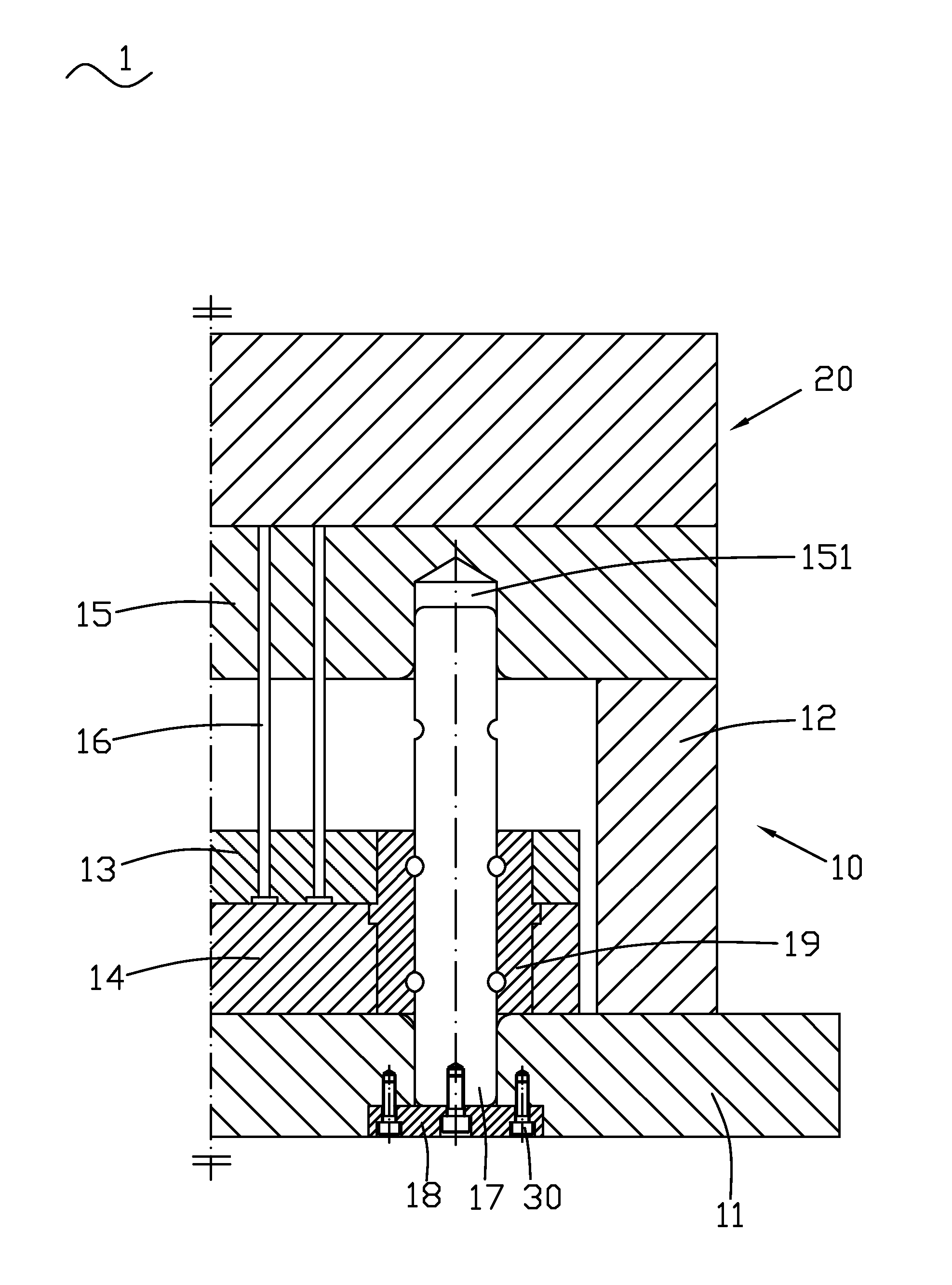
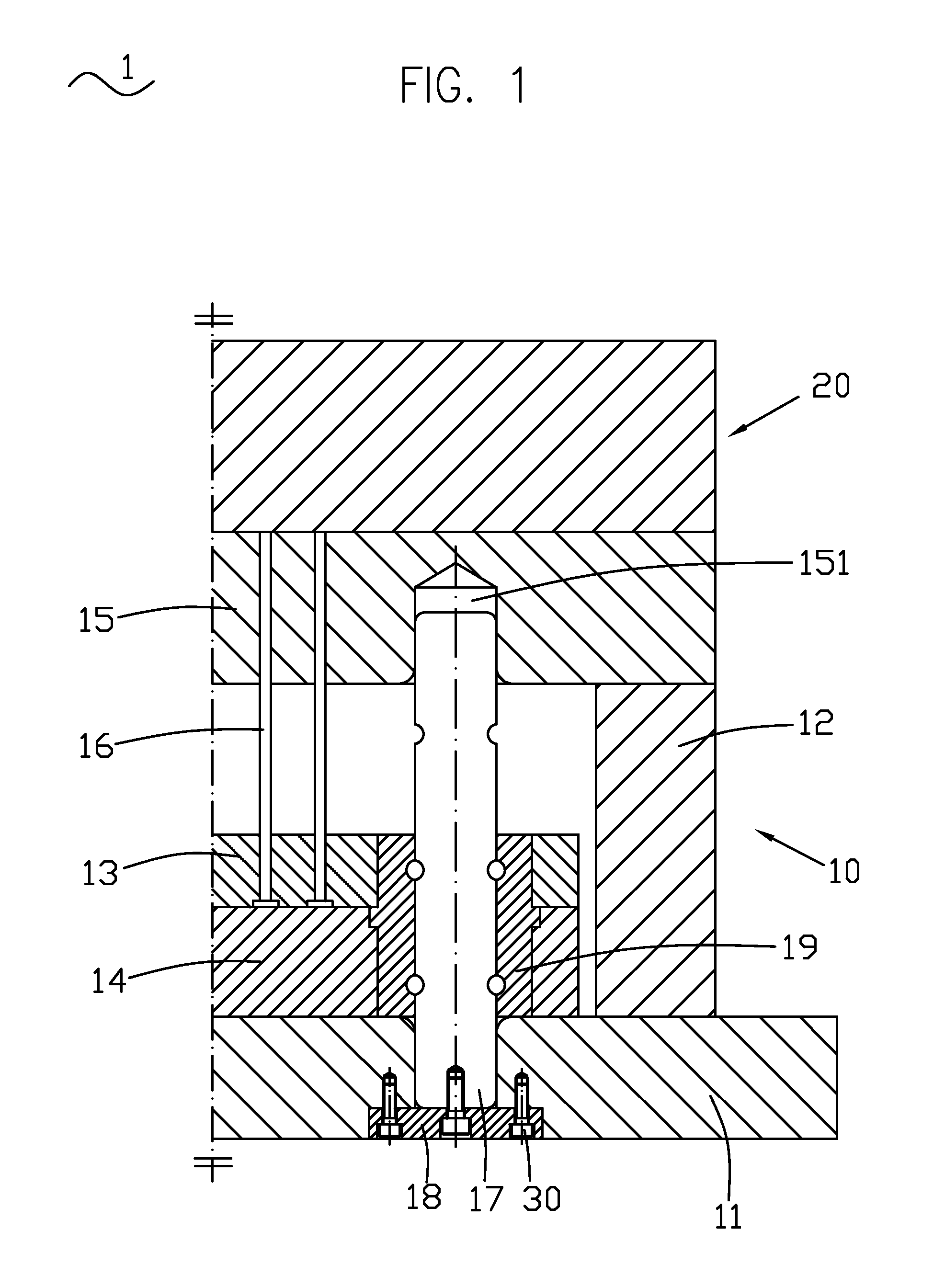
[0017]Referring to FIG. 1, the present invention provide a method for assembling an injection mold, which is indicated at 1 in the drawings. The injection mold 1 comprises a movable die 10 and a stationary die 20.

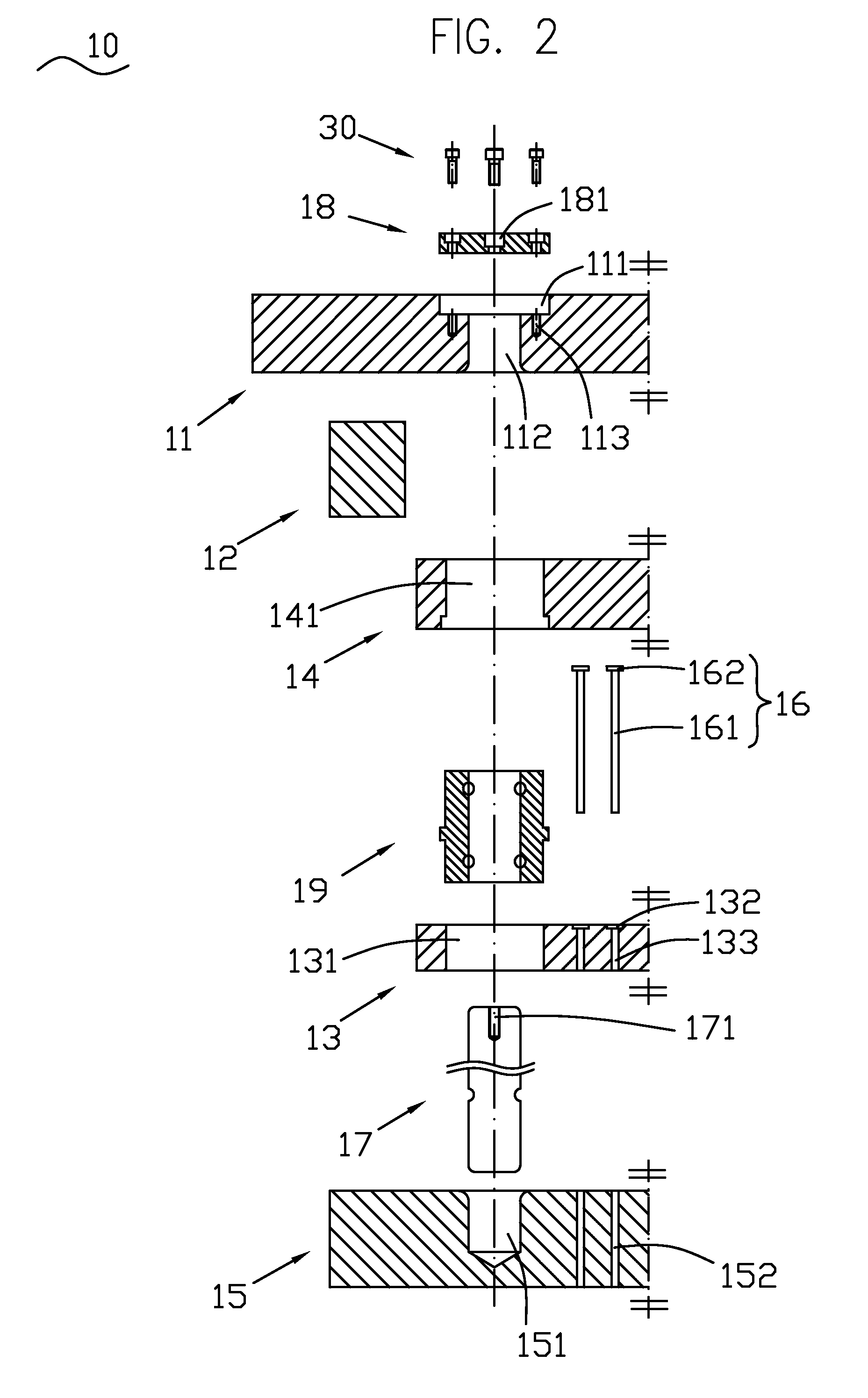
[0018]Referring to FIGS. 1 and 2, the movable die 10 comprises a movable die fixing plate 11, two spacer plates 12, an ejection pin plate 13, an ejection pin fixing plate 14, a punch template 15, a plurality of ejection pins 16, a plurality of guide rods 17, a press plate 18, and a plurality of guide bushes 19. The movable die fixing plate 11 forms a concave trough 111. A middle portion of a bottom of the concave trough 111 forms a holding bore 112. The holding bore 112 penetrates the movable die fixing plate 11. On the bottom of the concave trough 111, screw hol...


PUM

PropertyMeasurementUnit
elastic deformationaaaaaaaaaa

Abstract

An assembling method of an injection mold includes the steps of: disposing guide rods and a ejection pin plate on a punch template; inserting guide bushes into the ejection pin plate; inserting ejection pins respectively into the ejection pin plate and the punch template; fastening a ejection pin fixing plate to the ejection pin plate; fastening a die fixing plate and spacer plates to the punch template, and inserting the other ends of the guide rods into the die fixing plate; and disposing a press plate into the die fixing plate, and fastening the guide rods to the die fixing plate by tightening screws. The assembling method set the guide rods first o achieve a positioning function before ejection pin plate is assembled, and thereby capable of effectively eliminating the problems of deformation of the ejection pin plate, breaking of the ejection pin, and abrasion occurring in the return stroke.

Description

TECHNICAL FIELD OF THE INVENTION[0001]The present invention relates to an injection mold, and more particularly, to an assembling method of the injection mold.BACKGROUND OF THE INVENTION[0002]Referring to FIG. 3, a conventional injection mold 80 comprises a movable die 81 and a stationary die 82. The movable die 81 comprises a movable die fixing plate 811, a spacer plate 812, an ejection pin plate 813, an ejection pin fixing plate 814, a punch template 815, an ejection pin 816, and a guide rod 817. When the movable die 81 is assembled, it is general to insert the ejection pin 816 into ejection pin holes (not shown) of the ejection pin plate 813 and the punch template 815, and then fasten the ejection pin fixing plate 814 to the ejection pin plate 813 for preventing the ejection pin 816 from being ejected out. Then, the guide rod 817 is inserted into the punch template 815, the ejection pin fixing plate 814, the ejection pin plate 813, and the movable die fixing plate 811.[0003]Howev...

Claims


Application Information

Patent Timeline
Patent Type & Authority Patents(United States)
IPC IPC(8): B29C45/17B29C45/26B29C45/40
CPCB29C45/17B29C45/2602B29C33/30Y10T29/49947B29C45/4005Y10T29/49963B29C45/2606
Inventor LI, JIAN-MINGWU, XIAO-PINGHO, SHIH-HSIUNG
Owner CHENG UEI PRECISION IND CO LTD
Why Eureka
Try Eureka