
Aquaculture production system

a production system and aquaculture technology, applied in pisciculture, aquaria, climate change adaptation, etc., can solve the problems of escapism of non-native species into the environment, severe limitations of application of net pen/cage systems, environmental scrutiny, etc., to reduce energy consumption, economic and environmental superiority, and reduce stress on the structure of the tank

Inactive Publication Date: 2013-02-12
PAPADOYIANIS ERNEST D +1
View PDF28 Cites 13 Cited by
  • Summary
  • Abstract
  • Description
  • Claims
  • Application Information

AI Technical Summary

Benefits of technology

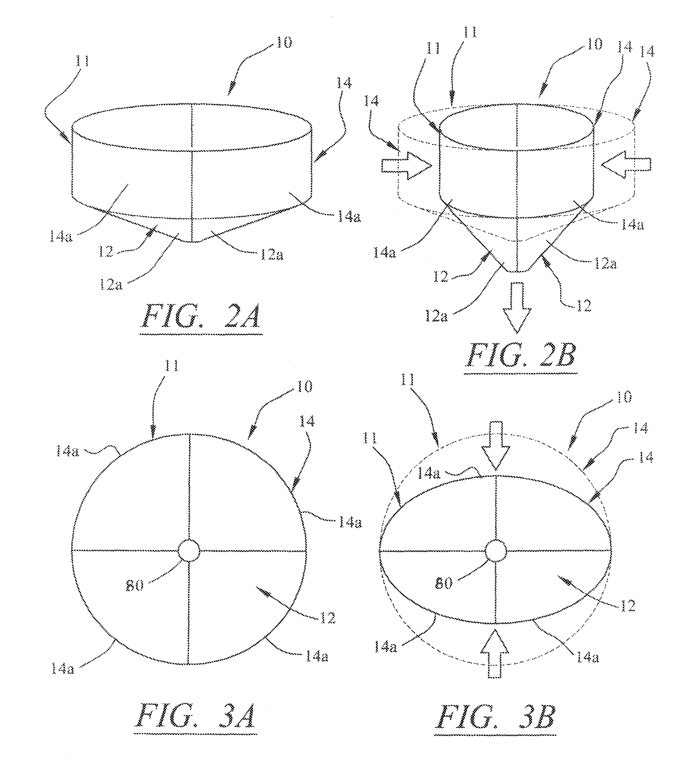
The patent is for a a unique aquaculture system that can be used in various water environments. The system consists of a cylindrical tank enclosure with flexible membranes that allow it to change shape and absorb external forces without getting damaged. The tank also has a conical-shaped bottom for efficient waste collection. The tank can be submerged and stabilized at different positions within the water. It can also be powered by solar energy panels or other power sources to provide oxygenated water for fish and aquatic life. Overall, the patent presents a versatility and flexibility in design and functionality for aquaculture production.

Problems solved by technology

Net pen / cage aquaculture has been practiced for thousands of years in freshwater lakes and nearshore ocean sites, however over the last 10 years has received tremendous criticism and environmental scrutiny for its highly pollutive effects, and escapism of non-native species into the environment.
Further, the pollutive nature of net pen / cage systems has severely limited their applications globally as they cannot be sited / positioned in closed bodies of water such as lakes; areas with low current / tidal exchange; or environmentally sensitive areas.
The '024 patent has a disadvantage in that the tank has a rigid wall that does not articulate and deform in order to absorb the impact of waves and wind.

Method used


Image

  • Aquaculture production system
  • Aquaculture production system
  • Aquaculture production system

Examples


Embodiment Construction

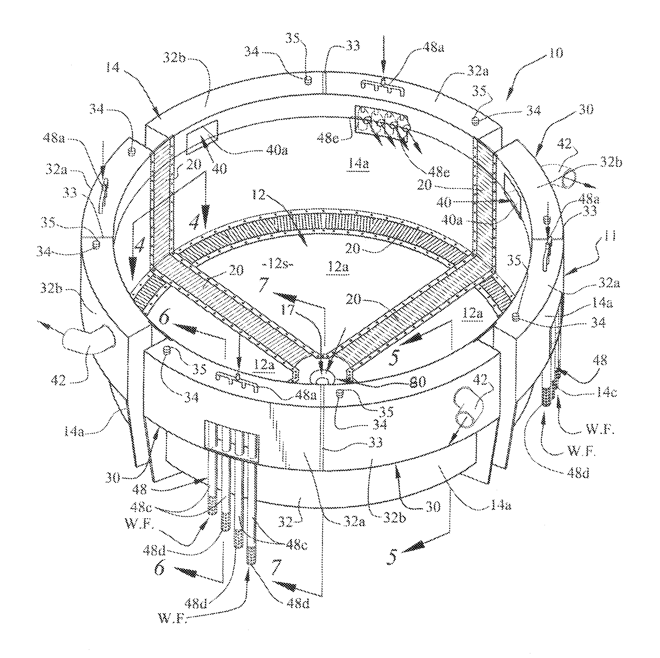
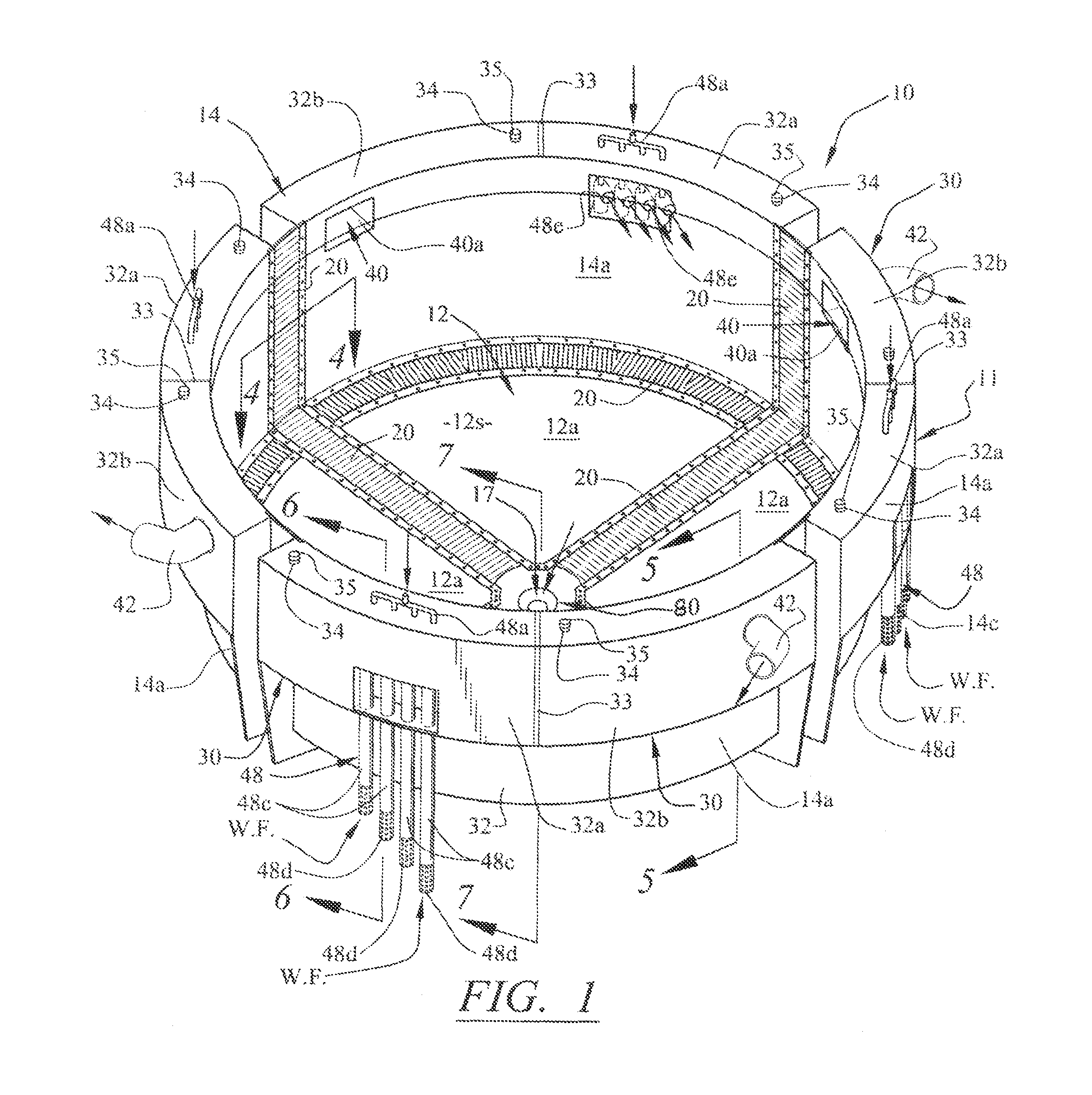
[0044]The entire floating fish production system is shown in FIGS. 10 and 12 and is generally indicated as 1. Referring initially to FIG. 1, the fish production system 1 includes at least one primary containment tank (also referred to interchangeably as “aquaculture tank”), generally indicated as 10. The primary containment tank 10 is defined by a tank body 11 that has a floor structure 12 and a wall structure 14 extending upwardly from the floor structure 12 to an open top which may be covered by a dome shaped netting or mesh 15, as generally depicted in FIGS. 10 and 12. The floor structure 12 and wall structure 14 surround a tank interior 16 that is adapted to be filled with water taken from a surrounding body of water within which the containment tank 10 is partially submerged, as shown in FIG. 10. The tank interior 16, when filled with water, is adapted for containing fish and other aquatic animal, plant, and algal species, with the primary purpose of producing fish, shrimp, mol...


PUM


Abstract

A floating fish production system for placement within a body of water and being structured and disposed for containing fish and other aquatic animal, plant and algal species, the system including at least one primary containment tank having an arrangement of individual solid wall sections and an arrangement of individual solid floor sections. Flexible membranes span between and connect to adjacently positioned solid wall and floor sections to define flexible connecting joints that allow the individual solid wall and floor sections to move relative to one another in an articulating action. The flexible membranes allow the tank configuration to temporarily deform from a relaxed state in response to externally applied forces exerted on the tank (e.g., waves, wind, current) to thereby absorb the externally applied forces and reduce stress on the structural integrity on the tank. An air lift system including a high volume, low pressure blower and a spaced arrangement of vertically extending air lift pipes delivers water and oxygen from the exterior body of water and into the tank interior. A flexible main drain in a central area at the bottom of the tank connects to a waste recovery system for removing waste produced by the fish and other aquatic species.

Description

[0001]This application is a Continuation-In-Part (CIP) of U.S. patent application Ser. No. 11 / 307,013 filed on Jan. 19, 2006, now abandoned, which was based on Provisional Patent Application Ser. No. 60 / 650,296 filed on Jan. 26, 2005.BACKGROUND OF THE INVENTION[0002]1. Field of the Invention[0003]The present invention relates generally to fish containment systems, tanks, structures, net enclosures, pens and cages or other defined containers, and more particularly to buoyant aquaculture systems, cages, self-contained housings, and floating containment structures for rearing fish, invertebrates, algae, seaweeds, and the like.[0004]2. Discussion of the Related Art[0005]In recent years, the importance of fish in human diets has attained renewed recognition due to dietary research comparing the health benefits, as well as negative health impacts, of fish and other meats. Consumer demand for fish has increased, and commercial farmers have searched for new techniques for producing more fis...

Claims


Application Information

Patent Timeline
Patent Type & Authority Patents(United States)
IPC IPC(8): A01K63/00
CPCA01K61/007A01K61/60Y02A40/81
Inventor PAPADOYIANIS, ERNEST D.CHERCH, XAVIER T.
Owner PAPADOYIANIS ERNEST D
Learn More