Valve for a container for dispensing pressurized fluid

a technology for valves and containers, applied in valve details, liquid dispensing, couplings, etc., can solve the problem of not being able to ensure the complete closing of the valve, and achieve the effect of facilitating the cured fluid

Active Publication Date: 2013-02-12
C EHRENSPERGER
View PDF12 Cites 8 Cited by
  • Summary
  • Abstract
  • Description
  • Claims
  • Application Information

AI Technical Summary

Benefits of technology

[0016]According to another advantageous configuration of the invention, the gap between the sealing lip and the retaining lip and / or the width of the disc-shaped sealing lip with respect to the disc-shaped retaining lip and / or the thickness of the sealing lip as compared to the retaining lip are designed such that the sealing lip may be deformed in the valve seat and an outer, leading edge facing the retaining lip abuts on said retaining lip or may be arranged at a close distance thereof. This configuration has the advantage that in the gap formed between the sealing lip and the retaining lip an undercut is realised in order to safely accommodate the cured fluid.
[0017]An analogous assembly is preferably provided for the retaining lip in relation to the punch portion on the closure member. Thus, it is advantageously achieved that a gap between the punch portion and the retaining lip equally acts as an undercut for safely accommodating the at least one remainder of cured fluid. In addition, because of the recesses existing between the anchoring elements, the cured fluid formed between the retaining lip and the sealing lip and the one formed between the punch portion and the retaining lip are allowed to form land-shaped connecting portions between each other, such that the entire zone which adjoins the sealing lip and which is subject to the risk of a formation of at least one remainder of cured fluid, is interconnected by lands and is fixed with respect to the valve body at least by positive engagement due to undercuts.
[0018]According to a further preferred configuration of the invention, the retaining lip is designed to be arranged at a distance from the valve seat and preferably with a gap separating it from a lateral area of the passage surrounding the closure member when the closure member is in a closing position. Thus, it is possible that on an opening movement the cured fluid which may have formed on the retaining lip is immediately lifted off from the passage. Thus, the remainders of cured fluid are prevented from breaking and causing damage to the valve.
[0019]According to a further preferred configuration of the invention, the at least one retaining lip is integrally formed with the closure member. Thus they may be fabricated in a simple manner as an injection-moulded part.
[0020]Alternatively, the at least one retaining lip may be designed to be formed as a slip-on ring. Thus, it is possible to achieve greater flexibility as far as the configuration of the ring is concerned.

Problems solved by technology

This may cause damage to the valve seat and / or the sealing lip, such that a complete closing may no longer be ensured.
Thus, either pressurised fluid may continue to escape or air may enter into the interior of the container due to the non tightly sealing valve and cause a curing of the fluid inside the container.

Method used


Image

  • Valve for a container for dispensing pressurized fluid
  • Valve for a container for dispensing pressurized fluid
  • Valve for a container for dispensing pressurized fluid

Examples


Embodiment Construction

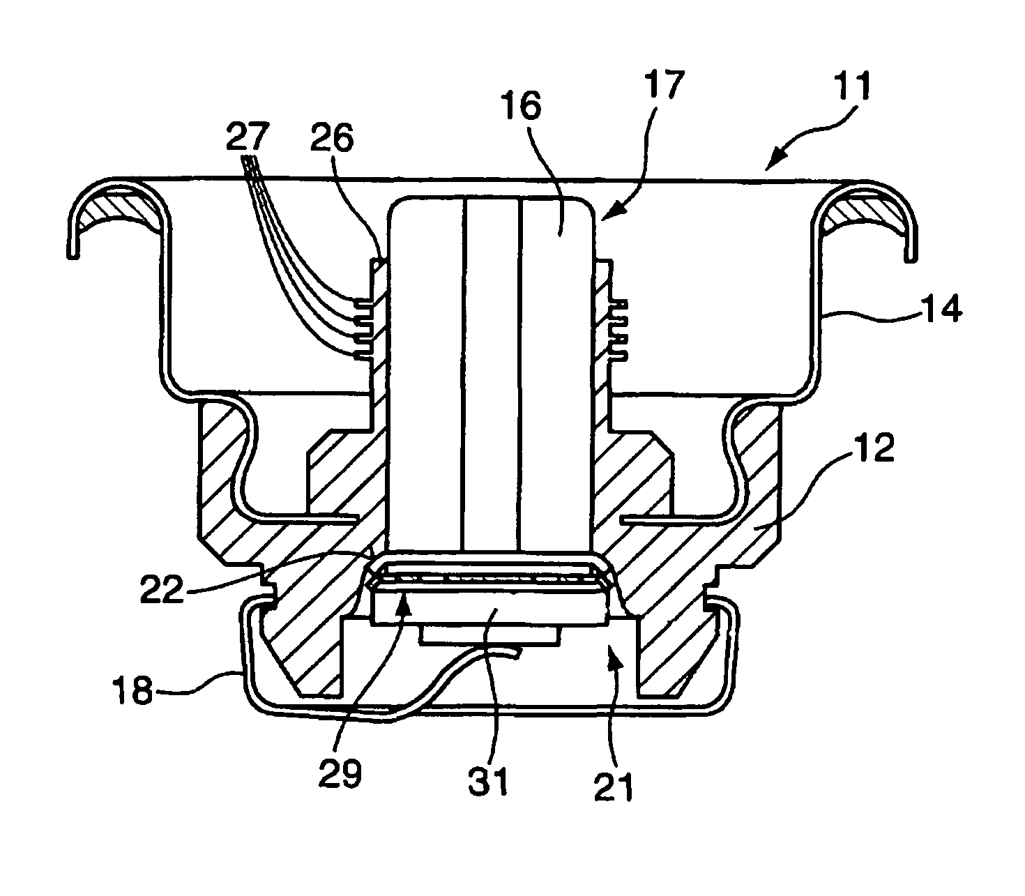
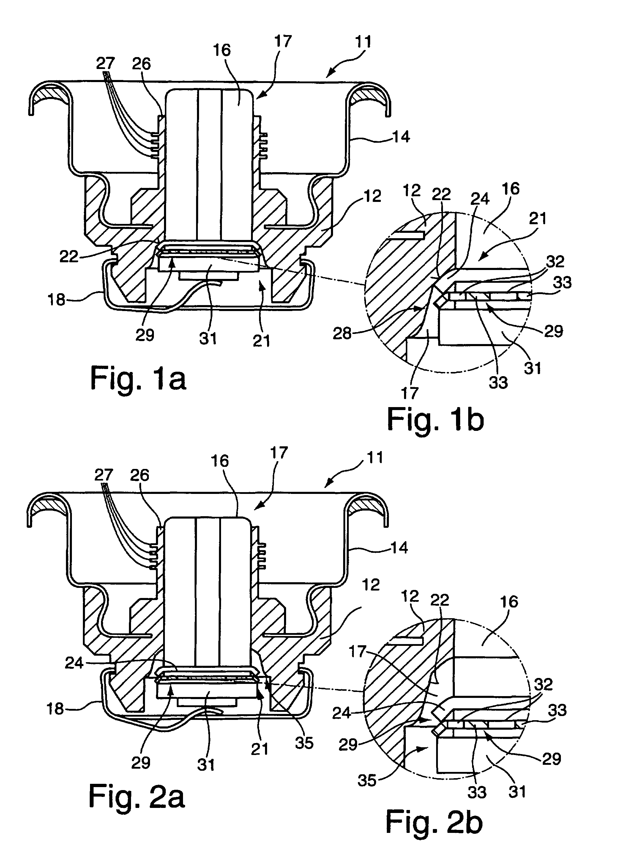
[0030]FIG. 1a represents a schematic sectional view of a valve 11 according to the present invention. A valve11 of this type comprises a valve body 12 on which a container lid 14 of a container, not shown in greater detail, may be arranged, or with which it is integrally formed or to which it is rigidly connected. A container of this type is preferably designed to hold pressurised fluids. The container serves in particular for storing and discharging fluids set under pressure by means of compressed air or by means of a propellant. Fluids preferably used include self-curing polyurethane foams, highly active polyurethane foams and adhesives.

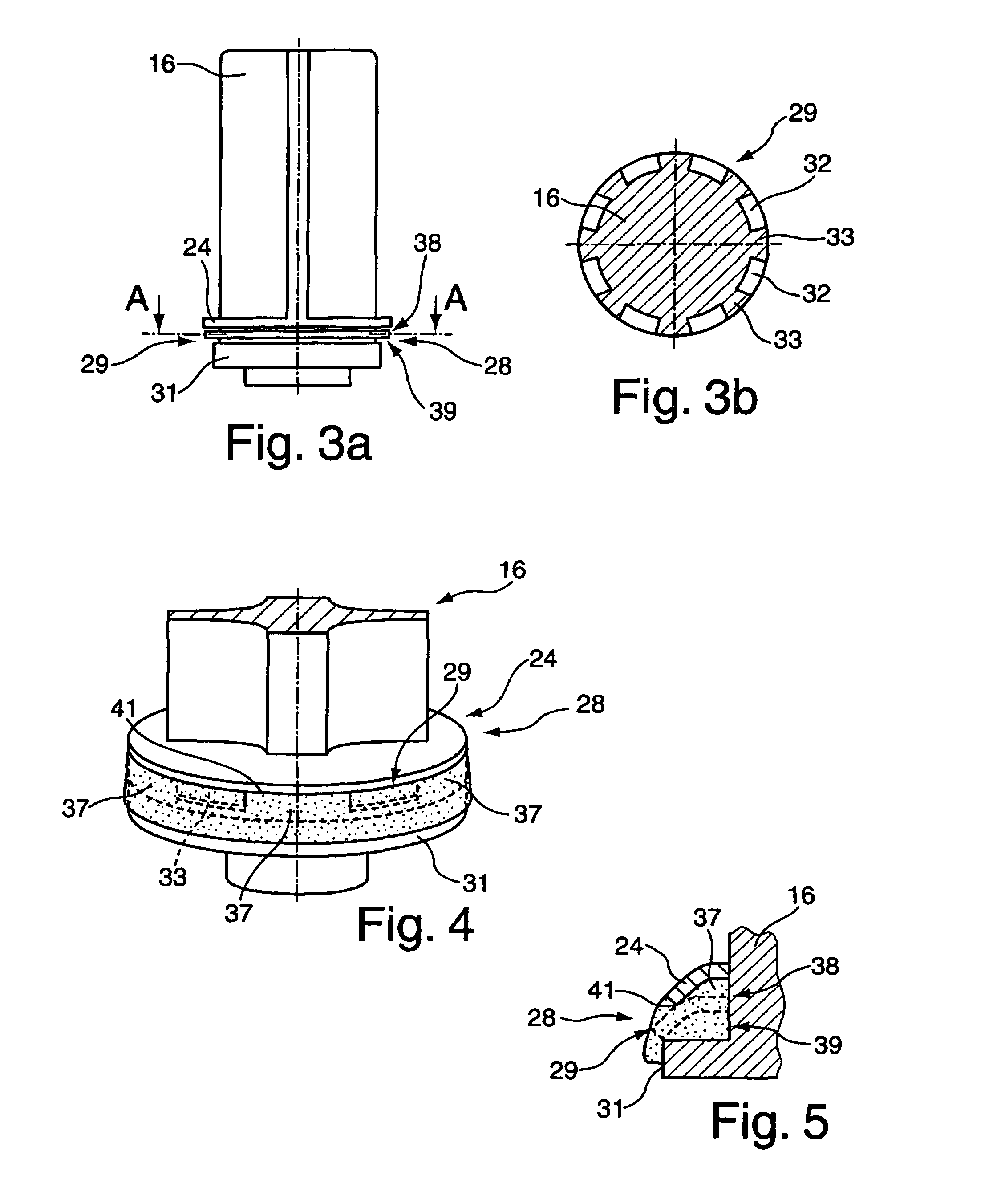
[0031]The valve body 12 accommodates a closure member 16 within a passage 17. A holding means 18, preferably a spring-like clamp, is applied to the valve body 12, so as to position the closure member 16 in a closing position 21 with respect to the valve seat 22 on the valve body 12 when it is in a normal, non-actuated position. The closure member 1...


PUM

PropertyMeasurementUnit
distanceaaaaaaaaaa
circumferenceaaaaaaaaaa
thicknessaaaaaaaaaa

Abstract

The invention relates to a valve for a container for dispensing pressurized fluid, the valve having a valve body which is mountable on a container lid, a closure member which is arranged in a passage provided in the valve body, a sealing arranged on the closure member and formed of at least one disc-shaped sealing lip and which, when the closure member is in a closing position relative to the valve body, abuts on a valve seat provided on the passage, and a holding device by which the closure member is displaceably arranged in the valve body and held in a closing position therein when it is in its normal position, at least one wear protection device being associated with the at least one sealing lip upstream with respect to the outflow direction of the fluid.

Description

CROSS-REFERENCE TO RELATED APPLICATIONS[0001]The present application claims the benefit under 35 U.S.C. 119 of the following foreign priority application, the disclosure of which is hereby incorporated by reference: German Patent Application No. 10 2008 051 888.3, filed Oct. 16, 2008.BACKGROUND OF THE INVENTION[0002]The invention relates to a valve for a container for dispensing pressurized fluid according to the preamble of claim 1.[0003]A valve of this type is known from EP 0 350 779 B1. This valve comprises a valve body which may be mounted on a container lid. The container lid is fastened on a container, usually on a can. The valve body accommodates a closure member which is arranged in a passage of the valve body. The closure member is provided with a sealing which consists of at least one sealing lip. When the closure member is in a closing position, the sealing abuts on a valve seat provided in the passage of the valve body and closes the passage. By means of holding means wh...

Claims


Application Information

Patent Timeline
Patent Type & Authority Patents(United States)
IPC IPC(8): B65D83/00
CPCB65D83/48
Inventor KOPP, VOLKER
Owner C EHRENSPERGER
Why Eureka
Try Eureka