
Electrical connector having a board connection leg portion with a locking portion to engage a signal transmission medium and a connector main body with an unlocking portion

a technology of electrical connectors and connectors, which is applied in the direction of fixed connections, coupling device connections, engagement/disengagement of coupling parts, etc., can solve the problems of insufficient holding force of signal transmission mediums, inability to achieve sufficient holding force of signals, and inability to achieve electrical connection stability

Inactive Publication Date: 2013-02-12
DAIICHI SEIKO CO LTD
View PDF10 Cites 12 Cited by
  • Summary
  • Abstract
  • Description
  • Claims
  • Application Information

AI Technical Summary

Benefits of technology

The electrical connector described in this patent has a locking mechanism at its end that securely holds the signal transmission medium in place. This mechanism is made up of a flexible locking arm and a holding portion that works together to hold the medium in a stable position. The locking arm is made from a portion of the holddown and is designed to maintain the connection with low force and high reliability. Overall, the connector provides a low-cost, long-term solution for holding and releasing signal transmission mediums.

Problems solved by technology

In this case, since a locking portion provided in the connector main body portion is a separately-formed member, there is a tendency for the connector to become expensive as a whole due to increase in the number of parts.
Further, since the locking portion is configured to engage the signal transmission medium by its own weight, there is the problem that a holding force to the signal transmission medium cannot sufficiently be obtained.
However, since a direction in which the elastically-supporting piece applies a pressing force and a soldered portion of the reinforcing bracket are in a relationship of positional deviation, there is such a possibility that according to a repetitive unlocking operation of a locking portion, an unlocking-operation force continuously applied to a connector main body portion affects a mounted state or the like of the connector main body portion, which results in lack of stability in electrical connection.

Method used


Image

  • Electrical connector having a board connection leg portion with a locking portion to engage a signal transmission medium and a connector main body with an unlocking portion
  • Electrical connector having a board connection leg portion with a locking portion to engage a signal transmission medium and a connector main body with an unlocking portion
  • Electrical connector having a board connection leg portion with a locking portion to engage a signal transmission medium and a connector main body with an unlocking portion

Examples


Embodiment Construction

[0042]Embodiments of the present invention applied to a plug connector will be described below in detail with reference to the drawings.

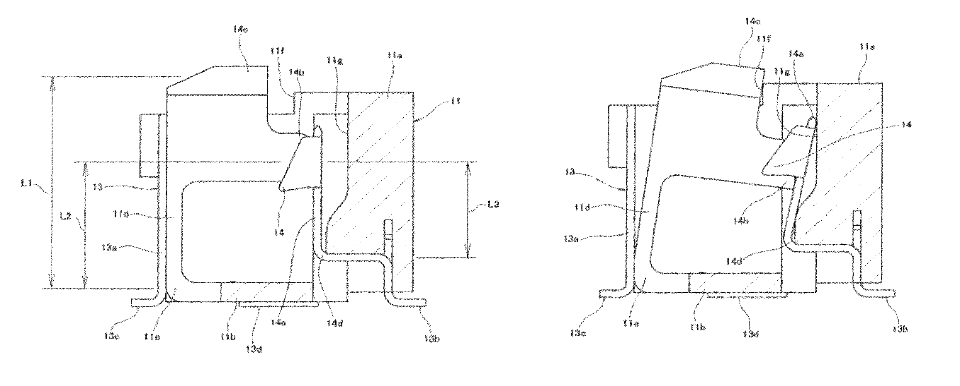
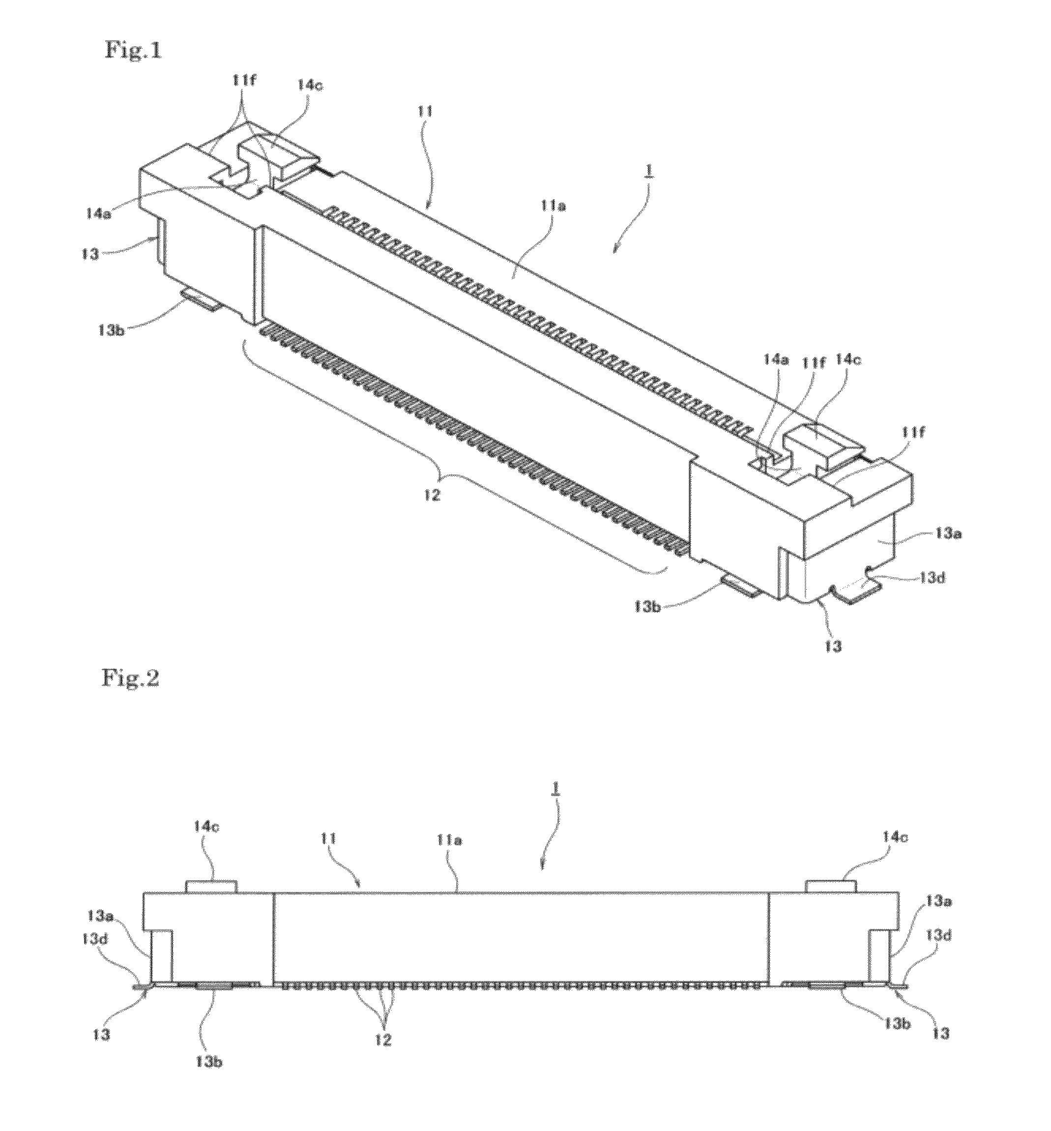
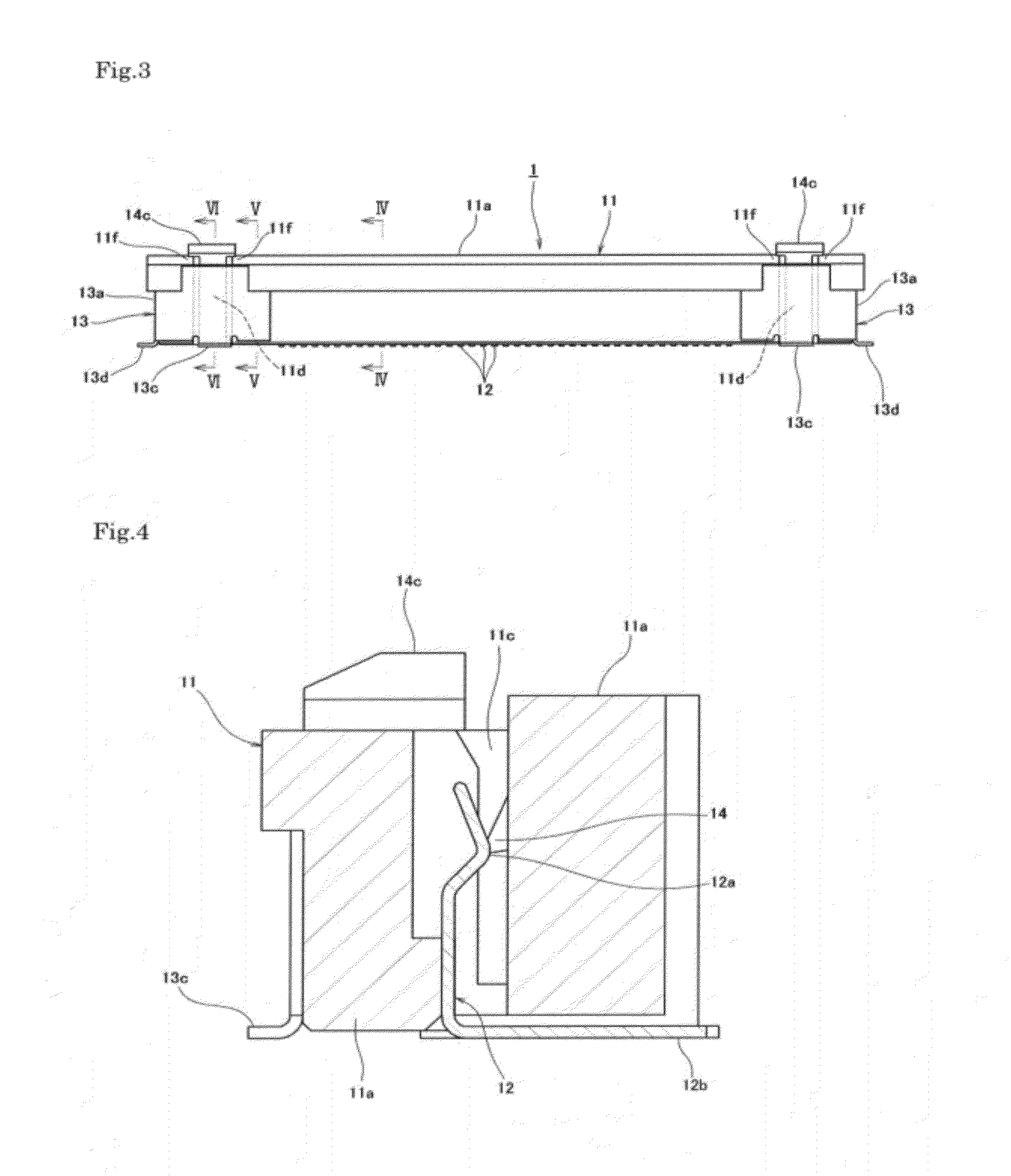
[0043]An electrical connector 1 according to an embodiment of the present invention shown in FIGS. 1 to 11 is an electrical connector mounted on a circuit board (not shown) constituting a portion of an electronic circuit of an electrical product, and the electrical connector 1 includes a connector main body portion 11 disposed so as to rise from a surface of the circuit board disposed substantially horizontally. The connector main body portion 11 is provided with an insulating housing 11a extending in an elongated shape along the surface of the circuit board.

[0044]In what follows, explanation is made under the assumption that the surface of the circuit board (not shown) extends horizontally, a direction in which the connector main body portion 11 rises from the surface of the circuit board is defined as “upward direction”, and the opposite direction...


PUM


Abstract

A signal transmission medium inserted in a connector main body portion, which can be held and released successfully with a simple configuration, is disclosed. A distal end portion of an elastically-displaceable cantilever-shaped locking arm member formed so as to be integral with a board connection leg portion (holddown) is provided with a locking portion engaged with a portion of the signal transmission medium inserted in the connector main body portion to hold the inserted state. The held state of the signal transmission medium is maintained by elastic action of the locking arm member extending in a relatively-elongated shape from a swinging fulcrum. Simultaneously, an unlocking-action force on the locking portion can be reduced, and an unlocking-operation force is stably received by the board connection leg portion (holddown) fixed to a printed circuit board so that improvement in strength is achieved.

Description

BACKGROUND OF THE INVENTION[0001]1. Field of the Invention[0002]The present invention relates to an electrical connector configured to hold a signal transmission medium inserted in a connector main body portion with a lock portion.[0003]2. Description of the Related Art[0004]Conventionally, various electrical devices or the like adopt an electrical connector that connects a signal transmission medium, such as a flexible flat cable (FFC) or a flexible printed circuit board (FPC), electrically to a circuit board. This electrical connector is mounted such that a connector main body portion rises from a surface of the circuit board, for example, via a board connecting leg portion (holddown) joined to the circuit board, and configured to achieve electrical connection by inward insertion of a signal transmission medium through an insertion opening portion provided in the connector main body portion of the electrical connector.[0005]In a terminal portion in an insertion side of the signal ...

Claims


Application Information

Patent Timeline
Patent Type & Authority Patents(United States)
IPC IPC(8): H01R13/62
CPCH01R12/61H01R12/727H01R13/639H01R12/774H01R12/87H01R12/77H01R13/629
Inventor ISHIMARU, MASAO
Owner DAIICHI SEIKO CO LTD
Learn More