Shift control of continuously variable transmission

a technology of transmission and shift control, which is applied in the direction of road transport, instruments, gearing, etc., can solve the problems of shifting shock, inability to coordinate the upshift in the subtransmission mechanism, and inability to control the rotation speed of the internal combustion engine, so as to reduce the rotation variation and increase the amount of fuel consumed.

Active Publication Date: 2013-02-12
NISSAN MOTOR CO LTD +1
View PDF72 Cites 0 Cited by
  • Summary
  • Abstract
  • Description
  • Claims
  • Application Information

AI Technical Summary

Benefits of technology

[0012]It is therefore an object of this invention to suppress both rotation variation in an internal combustion engine accompanying an upshift in a subtransmission mechanism and an increase in an amount of fuel consumed by the internal combustion engine during a shift operation in the continuously variable transmission.

Problems solved by technology

However, it is difficult to coordinate the upshift in the subtransmission mechanism and the downshift in the continuously variable transmission perfectly, and therefore temporary variation in the rotation speed of the internal combustion engine is inevitable.
This rotation variation causes shift shock.
However, when the continuously variable transmission is constituted by a belt type continuously variable transmission and the continuously variable transmission is operated in the vicinity of the minimum speed ratio, a fuel consumption amount of the internal combustion engine increases in comparison with a case in which the continuously variable transmission is operated at a speed ratio close to 1.0.
Hence, when the continuously variable transmission is operated in the vicinity of the minimum speed ratio, a load of a hydraulic pump that supplies the oil pressure increases, and as a result, the fuel consumption amount of the internal combustion engine that drives the hydraulic pump inevitably increases in comparison with a case where the continuously variable transmission is operated at a speed ratio close to 1.0.

Method used


Image

  • Shift control of continuously variable transmission
  • Shift control of continuously variable transmission
  • Shift control of continuously variable transmission

Examples


second embodiment

[0120]Next, referring to FIG. 10, this invention will be described.

first embodiment

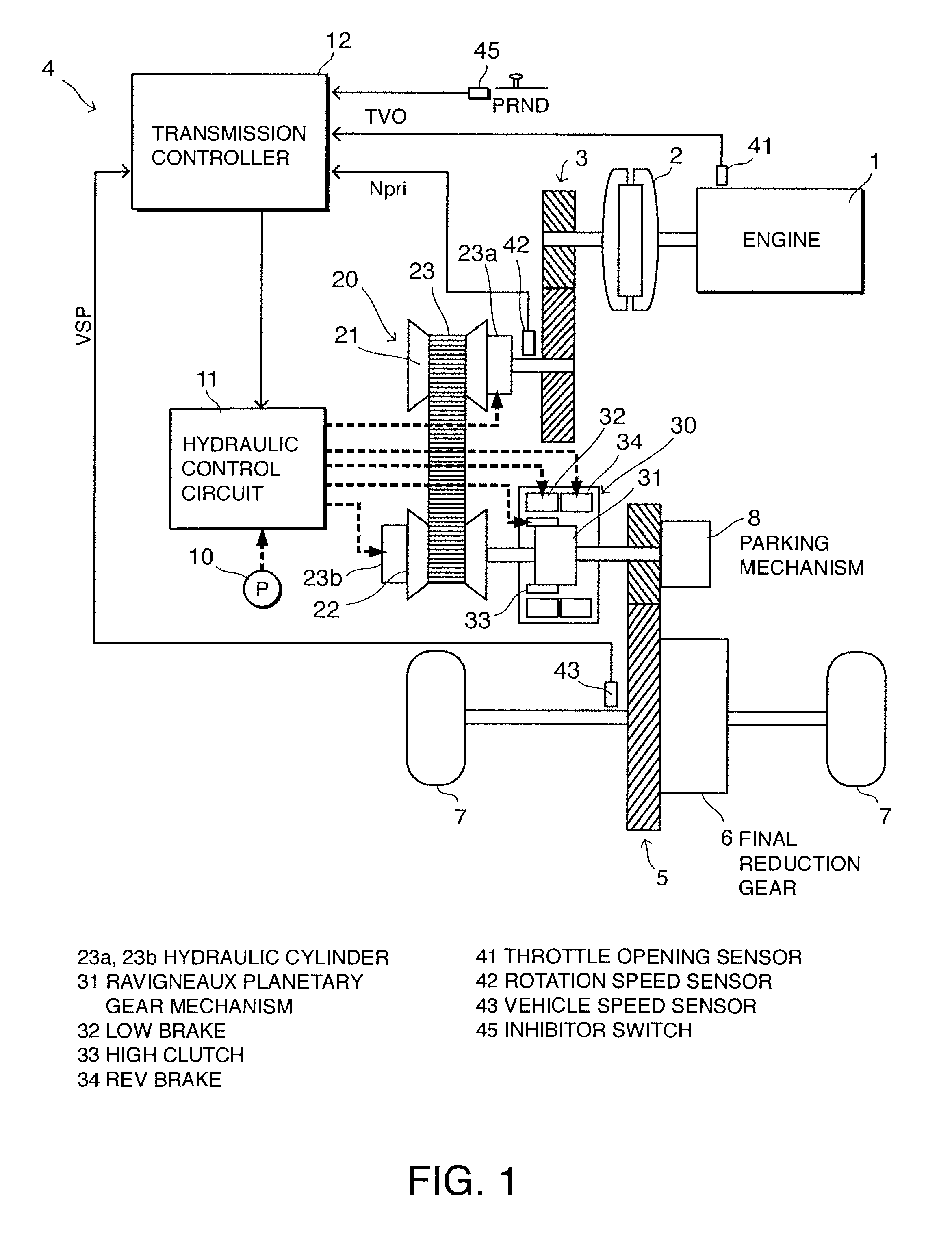
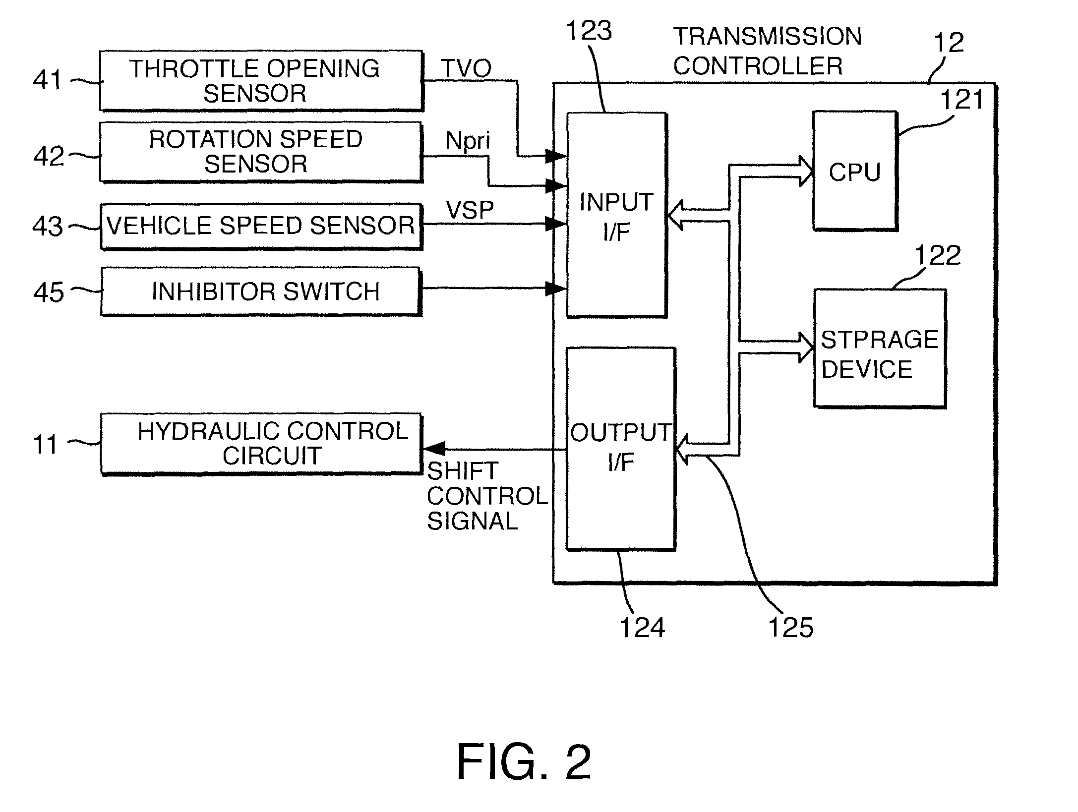
[0121]The hardware constitution of this embodiment is identical to that of the The shift controller 12 according to this embodiment performs upshift control on the subtransmission mechanism 30 using a shift map having the characteristics shown in FIG. 10 instead of the shift map having the characteristics shown in FIG. 5.

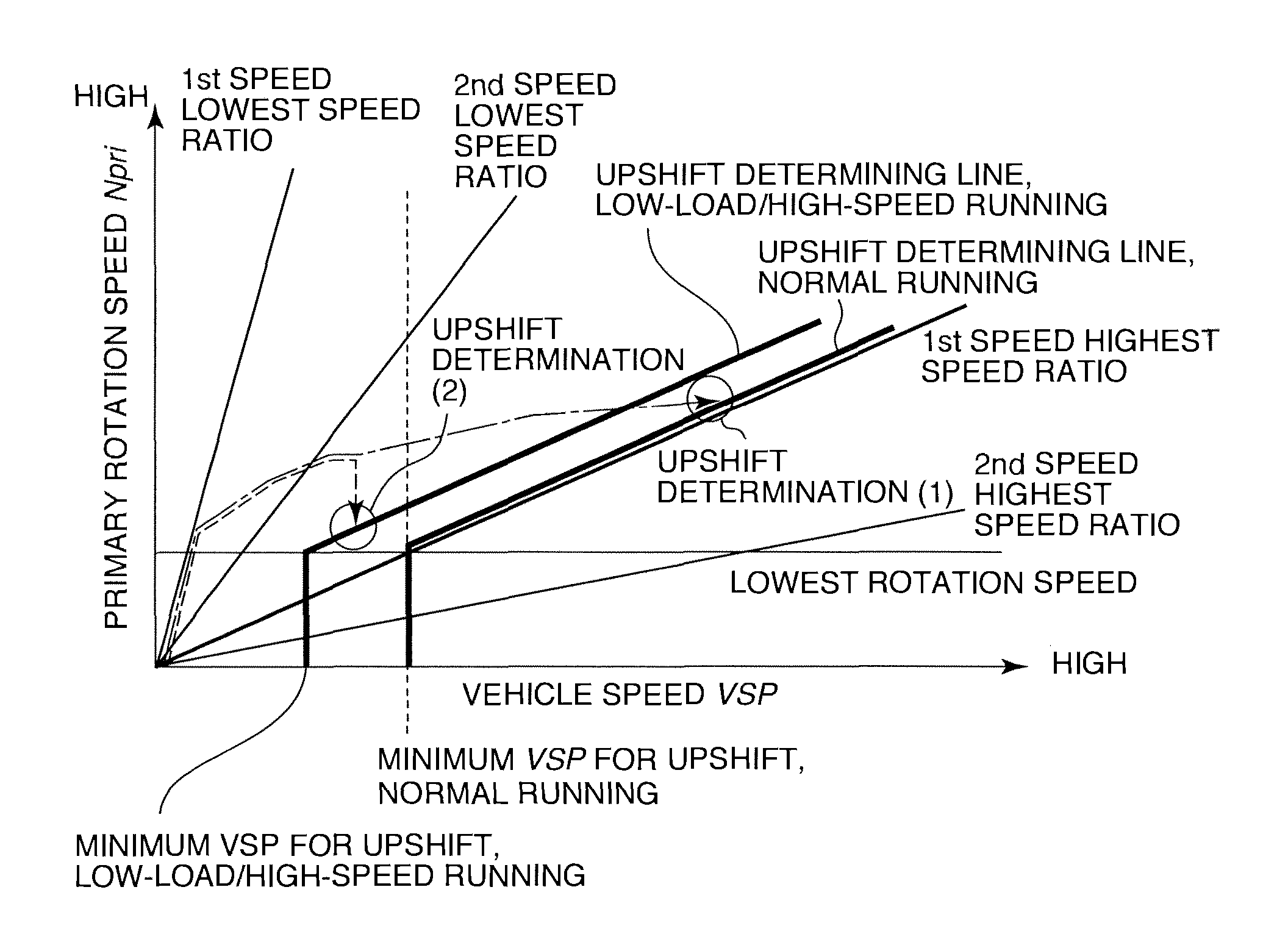
[0122]In the first embodiment, the shift controller 12 switches between the normal upshift determining line and the low load / high speed region upshift determining line, as shown in FIG. 5, whereas in this embodiment, the subtransmission mechanism 30 is upshifted using a single upshift determining line.

[0123]The minimum vehicle speed for an upshift on the single upshift determining line is set similarly to the minimum vehicle speed for an upshift on the low load / high speed region upshift determining line of the first embodiment. In the region where the primary rotation speed Npri is equal to or greater than the lowest rotation speed, the normal upshift determining l...


PUM


Abstract

A continuously variable transmission 4 for a vehicle includes a variator 20 that modifies a speed ratio continuously and a subtransmission mechanism 30 that is connected in series to the variator 20 and applies a first speed and a second speed, which is higher than the first speed, selectively. When the vehicle is running under a low load / high speed upshift condition having a lower load or a higher speed than a normal upshift condition, the subtransmission mechanism 30 is upshifted from the first speed to the second speed at a lower vehicle speed than under the normal upshift condition, and as a result, both rotation variation in an internal combustion engine 1 accompanying upshifting of the subtransmission mechanism 30 and an increase in a fuel consumption amount of the internal combustion engine 1 due to the shift operation in the continuously variable transmission 4 are suppressed.

Description

FIELD OF THE INVENTION[0001]This invention relates to shift control performed on a continuously variable transmission comprising a continuously variable transmission mechanism and a subtransmission mechanism.BACKGROUND OF THE INVENTION[0002]A continuously variable transmission is a transmission which is capable of varying a speed ratio continuously.[0003]In a vehicle installed with a continuously variable transmission, an internal combustion engine can be operated more efficiently than in a vehicle having a conventional stepped transmission, and therefore improvements in a power performance and a fuel performance of the vehicle can be expected.[0004]To improve the power performance and fuel efficiency performance of a vehicle installed with a continuously variable transmission even further, a possible speed ratio range (to be referred to hereafter as a “ratio range”) of the continuously variable transmission is preferably enlarged.[0005]When the ratio range of the continuously varia...

Claims


Application Information

Patent Timeline
Patent Type & Authority Patents(United States)
IPC IPC(8): F16H61/66F16H59/24F16H59/70F16H61/10F16H61/662F16H61/686
CPCF16H61/08F16H61/66259F16H61/6648F16H61/702F16H37/022Y10T477/6217F16H2037/023Y02T10/76Y10T477/623Y10T477/688F16H61/6625Y02T10/60
Inventor TAKAHASHI, SEIICHIROTANAKA, HIROYASUNONOMURA, RYOUSUKESEKI, JOUJIINOUE, TAKUICHIROINOUE, MAMIKOOCHIAI, TATSUO
Owner NISSAN MOTOR CO LTD
Why Eureka
Try Eureka