Method and apparatus for wrist arthroplasty

a wrist arthroplasty and wrist technology, applied in the field of prosthetic wrist implants, can solve the problems of patient discomfort, pain and difficulty in moving the wrist, patient without wrist motion, and severe restrictions on the use of the wris

Inactive Publication Date: 2013-02-12
BIOMET MFG CORP
View PDF81 Cites 3 Cited by
  • Summary
  • Abstract
  • Description
  • Claims
  • Application Information

AI Technical Summary

Benefits of technology

[0006]An implant for a wrist arthroplasty, such as a total or hemi-arthroplasty, is disclosed. Various embodiments include providing a hemi-arthroplasty included for either replacing the distal portions of the radius, ulna or both to articulate with natural portions of the carpal bone complex. Also, a hemi-arthroplasty prosthesis that includes replacing portions of only the carpal bone complex is disclosed. Alternatively, an arthroplasty may occur regarding the radius or ulna bones and the carpal bones to provide a substantially complete wrist art...

Problems solved by technology

In a variety of wrist disorders, patients may experience discomfort, pain and difficulty in moving the wrist.
This procedure, however, leaves the patient without motion in their wrist and thereby severely restricts the use of their wrist.
Several of the prior wrist implants have suffered from drawbacks including limited range ...

Method used


Image

  • Method and apparatus for wrist arthroplasty
  • Method and apparatus for wrist arthroplasty
  • Method and apparatus for wrist arthroplasty

Examples


sixth embodiment

[0102]A sixth embodiment is illustrated in FIGS. 13 and 14, and illustrates an alternately constructed radial implant 52e, wherein the bearing guide 62e is formed with an arcuate shape that is configured to matingly engage the curvilinear cut 300 of a resected radius 2a′. Those skilled in the art will appreciate that the curvilinear cut 300 will support the bearing guide 62e and thereby permit the radial implant 52e to be formed with a relatively lower profile as compared to the radial implant 52.

seventh embodiment

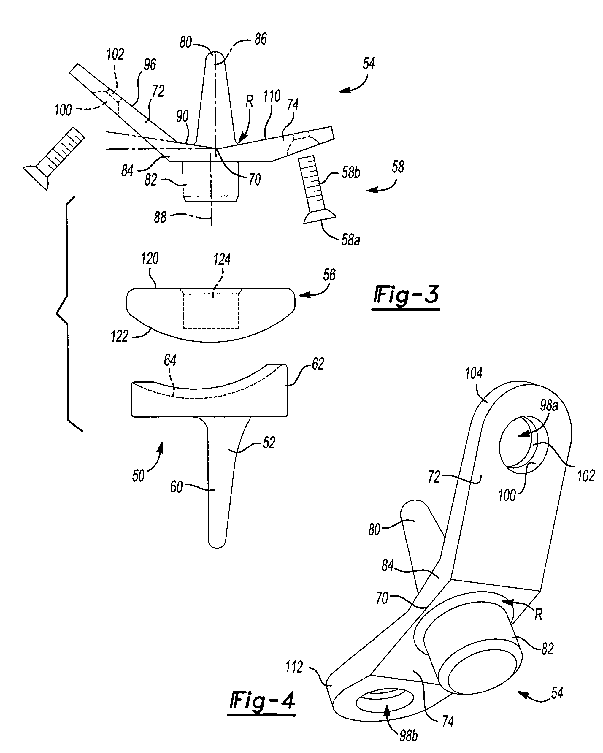
[0103]A seventh embodiment is illustrated in FIG. 15, wherein the prosthetic wrist 50f is illustrated to be generally similar to the prosthetic wrist illustrated in FIG. 8, except for the shape of the flange structure 200f and the wrist bearing component 56f. More specifically, the flange structure 200f includes a generally V-shaped interconnecting flange 84f to which the ulnar and radial flanges 72f and 74f, respectively, are oppositely coupled. As will be apparent to those skilled in the art, the wrist bearing component 56f is contoured to matingly engage the proximal side of the flange structure 200f and accordingly includes a generally V-shaped profile 400. In a manner that is similar to the prosthetic wrist of FIG. 8, the stem 80f includes a threaded end portion 220 that is threadably received into a threaded aperture 232 that is formed in the wrist bearing component 56f.

eighth embodiment

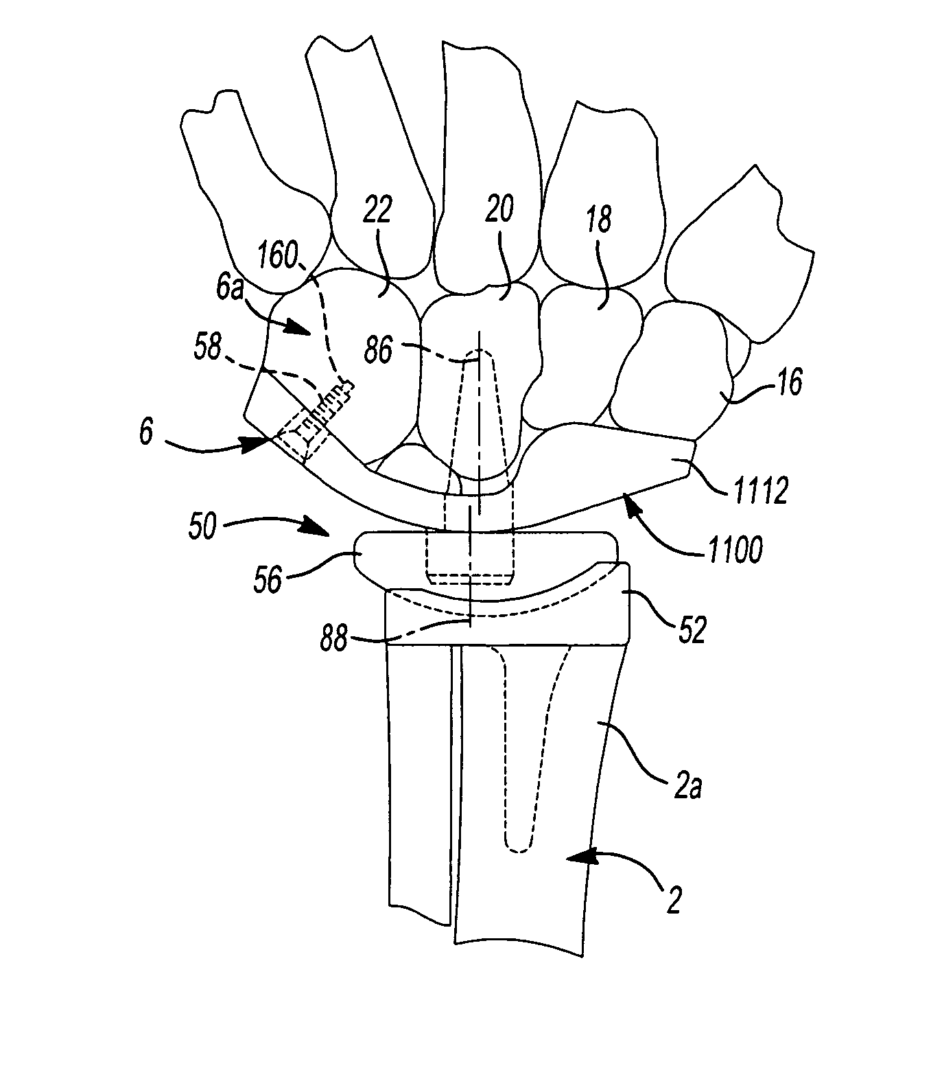
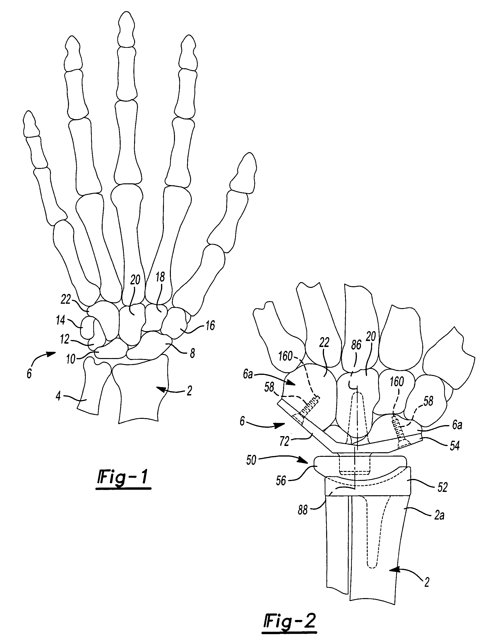
[0104]An eighth embodiment is illustrated in FIG. 16, which is similar to the prosthetic wrist of FIG. 8 except for the flange structure 200g. The flange structure 200g of the prosthetic wrist 50g includes an interconnecting flange 84g with an interconnecting bone abutment surface 90g with a plurality of portions 500 that are each defined by a skew angle. The skew angles that define each portion 500 need not be symmetrical about the stem axis 86g. The skew angle of each portion 500 is less than 90 degrees in magnitude to permit the interconnecting flange 84g to conform and abut the proximal end of the distal portion 6a (FIG. 2) of the carpal bone complex 6 (FIG. 2).


PUM


Abstract

A prosthetic wrist having at least one of a radial insert, which is configured to be fixed to a radius of a patient, a carpal implant or a wrist bearing component. The carpal implant can include a body and a pair of flanges, each of which being skewed to the axis of the body in a manner that permits them to abut the ulnar side of the hamate bone and the radial side of the distal portion of the carpal bone complex, respectively. The radial insert may be provided with a plurality of modular portions to allow for selection and customization of an implant. Also the various portions can allow for a hemi- or total, or revision wrist arthroplasty. The modular portions can allow for intraopertative customization.

Description

CROSS-REFERENCE TO RELATED APPLICATIONS[0001]This application is a continuation-in-part of U.S. patent application Ser. No. 10 / 862,821 filed on Jun. 7, 2005, which is a continuation-in-part of U.S. patent application Ser. No. 10 / 279,240 filed on Oct. 24, 2002. The disclosures of each of the above applications are incorporated herein by reference.FIELD[0002]The present teachings generally relate to prosthetic implants and more particularly to a prosthetic wrist implants.BACKGROUND[0003]With reference to FIG. 1 of the drawings, the dorsal side of the bone structure of a patient's left hand and wrist is illustrated in conjunction with the radius 2 and the ulna 4. The bone structure includes a carpal bone complex 6 having a scaphoid 8, a lunate 10, a triquetrum 12, a pisiform 14, a trapezium 16, a trapezoid 18, a capitate 20 and a hamate 22. It will be appreciated that the scaphoid 8 and the lunate 10 bones articulate with the radius 2 during the movement of the wrist.[0004]In a variety...

Claims


Application Information

Patent Timeline
IPC IPC(8): A61F2/42A61B17/80A61F2/00A61F2/02A61F2/30
CPCA61B17/80A61F2/0095A61F2/4261A61F2002/30171A61F2002/30179A61F2002/30354A61F2002/30383A61F2002/30448A61F2002/30507A61F2002/30535A61F2002/30538A61F2002/30578A61F2002/30604A61F2002/30614A61F2002/30616A61F2002/3065A61F2002/30654A61F2002/30662A61F2002/3069A61F2002/30787A61F2002/30841A61F2002/30884A61F2002/4264A61F2220/0025A61F2220/0033A61F2220/005A61F2230/0028A61F2230/005A61F2230/0058A61F2250/0006A61F2250/0058A61F2310/00023A61F2310/00029A61F2310/00161A61F2310/00179
Inventor SCHULTZ, JASON MPALMER, ANDREW KSTONE, KEVIN TGRAHAM, THOMAS JBERELSMAN, BRIAN KSTRICKLAND, JAMES W
Owner BIOMET MFG CORP
Why Eureka
Try Eureka