Wireless charging system with device power compliance

a charging system and power compliance technology, applied in the field of wireless power systems, can solve the problems of data communication corruption, inability to continuously run the pid control algorithm, etc., and achieve the effect of enhancing power compliance and reducing power level

Active Publication Date: 2013-02-12
PHILIPS IP VENTURES BV
View PDF26 Cites 57 Cited by
  • Summary
  • Abstract
  • Description
  • Claims
  • Application Information

AI Technical Summary

Benefits of technology

[0009]Consequently, the present invention provides enhanced power compliance within a wireless charging system. The system provides an indication of mismatches between power capacity and power requirements and also provides power distribution among multiple devices to enable multiple devices to be charged using a single power supply.

Problems solved by technology

The PID control algorithm is not run continuously, as this is more likely to result in corrupted data communication.

Method used


Image

  • Wireless charging system with device power compliance
  • Wireless charging system with device power compliance
  • Wireless charging system with device power compliance

Examples


Embodiment Construction

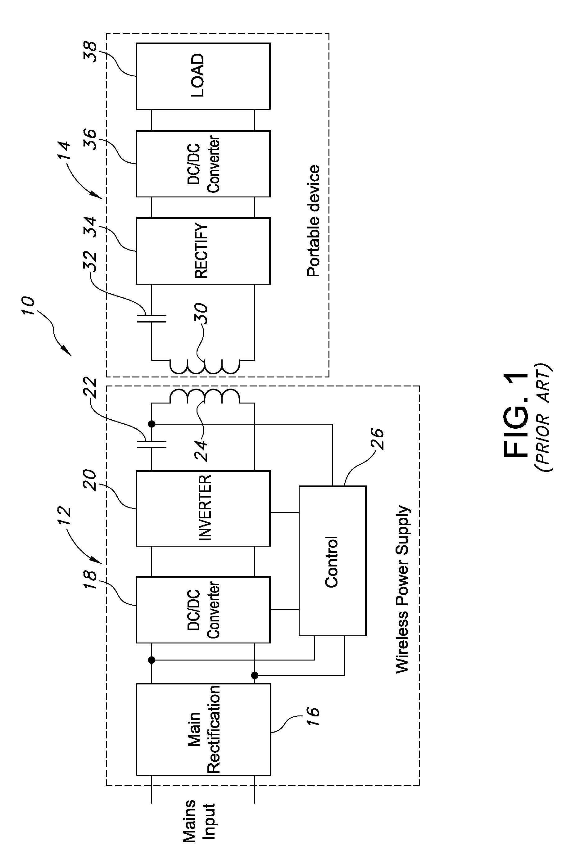
[0032]A prior art wireless charging system 10 is illustrated in FIG. 1 and includes a wireless power supply (WPS) 12 and a portable secondary device 14. The wireless power supply 12 in turn includes a rectifier 16, a DC / DC converter 18, an inverter 20, a capacitor 22, an inductive coil 24, and a control 26. The portable device 14 includes a secondary coil 30, a capacitor 32, a rectifier 34, a DC / DC converter 36, and a load 38. When the secondary coil 30 is brought into proximity to the primary coil 24, and when the primary coil is powered, an inductive link is established; and a voltage is induced in the secondary coil. The wireless charging system 10 as thus far described is well known and its structure and function need not be further described in detail.

[0033]Power systems such as that illustrated in FIG. 1 typically require the user to understand and remember what devices and what power supplies work together. Two different power supplies with different power capacities, but als...


PUM


Abstract

A method of controlling an inductive charging system on those occasions in which the combined power requests of a plurality of secondary devices exceed the power capacity of the power supply. The method includes at least one of (a) powering each device at a level below its requested level, (b) powering each device sequentially, and / or (c) powering each device in a repetitive pattern (e.g. time multiplexing). Also disclosed is a method of controlling an inductive charging system at least partially as a function of information received from the power management unit (PMU) of each secondary device.

Description

BACKGROUND OF THE INVENTION[0001]This application is related to U.S. application Ser. No. 12 / 349,355, entitled “Metered Delivery of Wireless Power” filed Jan. 6, 2009, now U.S. Pat. No. 8,069,100, which is incorporated by reference.[0002]The present invention relates to wireless power systems and more particularly to such systems capable of powering multiple devices simultaneously.[0003]Wireless power or charging systems are well known and widely used. Such systems typically include a primary power supply and one or more secondary devices. The primary inductively powers the secondary devices when they are brought into proximity with the primary.[0004]While such systems are well known, a number of potential problems are associated with such systems.[0005]First, each primary supply is typically sized for a particular application depending upon the power to be drawn from the power supply. Issues arise when the power requirements of the secondary devices are greater than the power capac...

Claims


Application Information

Patent Timeline
Patent Type & Authority Patents(United States)
IPC IPC(8): H02J7/00
CPCH02J5/005H02J7/0006H02J7/0052H01F38/14H02J7/025H02J7/00038H02J7/00H02J7/00047H02J50/402H02J50/80H02J50/10H02J50/12H02J50/40H04W4/80Y02D30/70
Inventor BAARMAN, DAVID W.MOLLEMA, SCOTT A.
Owner PHILIPS IP VENTURES BV
Why Eureka
Try Eureka