Wireless user interface for an HVAC controller and method of operating the same

a wireless remote control and user interface technology, applied in the field of heating/ventilation/air conditioning (hvac) systems, can solve the problems of increasing power consumption and cost, complex, powerful and power-consuming, etc., and achieve the effect of increasing the complexity and power of wireless remote control and increasing its power consumption and cos

Active Publication Date: 2013-02-19
LENNOX IND
View PDF17 Cites 32 Cited by
  • Summary
  • Abstract
  • Description
  • Claims
  • Application Information

AI Technical Summary

Benefits of technology

[0008]The motivation of the prior art has been to make wireless remote controls evermore complex and powerful to enable them to execute evermore complex and powerful control algorithms. Unfortunately, increasing the complexity and power of a wireless remote control increases its power consumption and cost. Rather than follow conventional thought, the present invention takes a contrary approach. The complexity and power required to control the HVAC system instead transferred to an HVAC controller that is physically wired to the HVAC system. Because the HVAC controller is wired to the HVAC system, it can be as complex, powerful and power-consumptive as needed. This frees the wireless remote control to become a mere wireless user interface to the HVAC controller, relaying user commands and temperature readings to the HVAC controller for further processing and control.

Problems solved by technology

Unfortunately, increasing the complexity and power of a wireless remote control increases its power consumption and cost.
Because the HVAC controller is wired to the HVAC system, it can be as complex, powerful and power-consumptive as needed.

Method used


Image

  • Wireless user interface for an HVAC controller and method of operating the same
  • Wireless user interface for an HVAC controller and method of operating the same
  • Wireless user interface for an HVAC controller and method of operating the same

Examples


Embodiment Construction

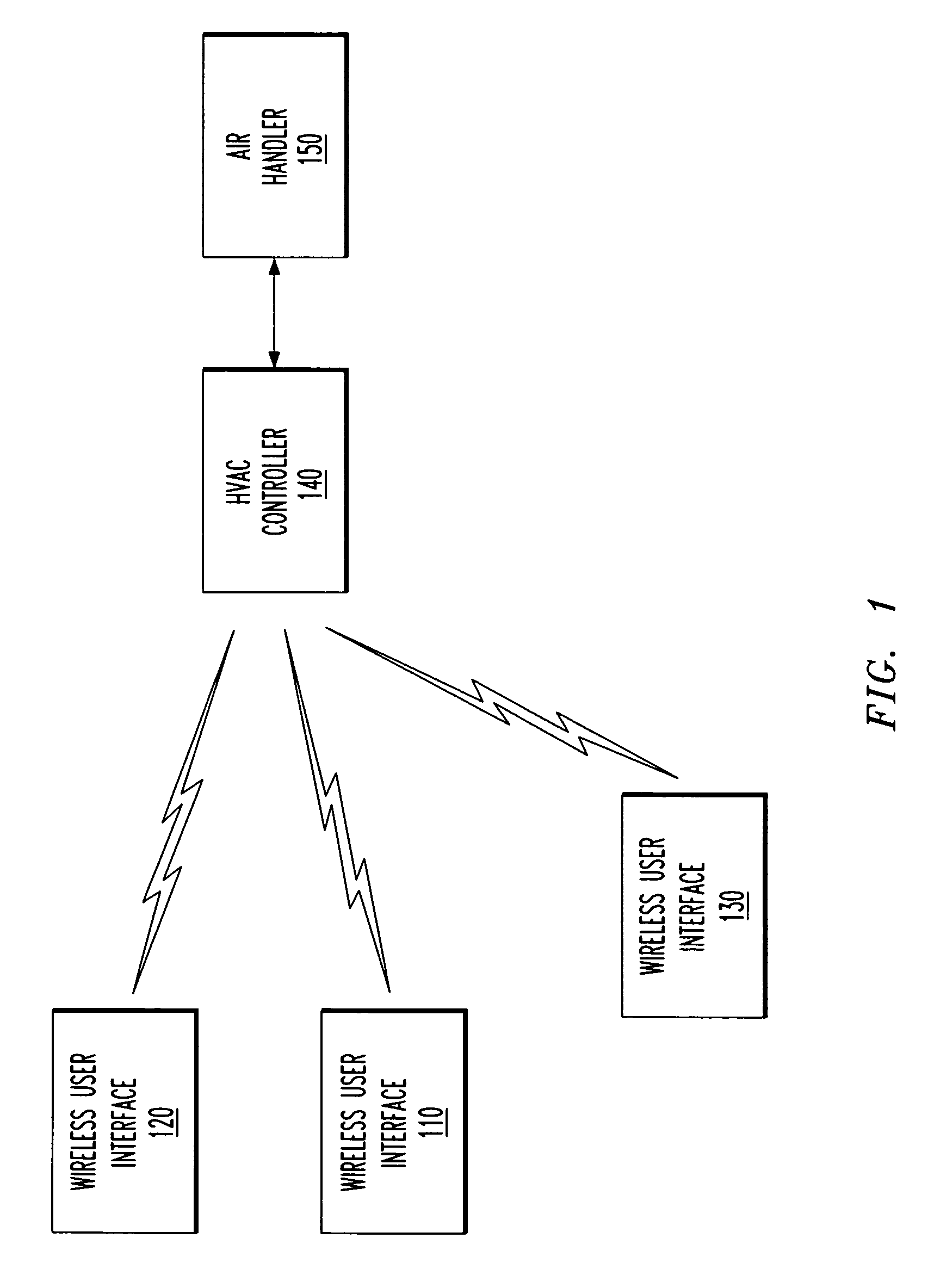
[0018]Referring initially to FIG. 1, illustrated is a block diagram of one embodiment of an HVAC system incorporating a wireless user interface constructed, or a method carried out, according to the principles of the present invention.

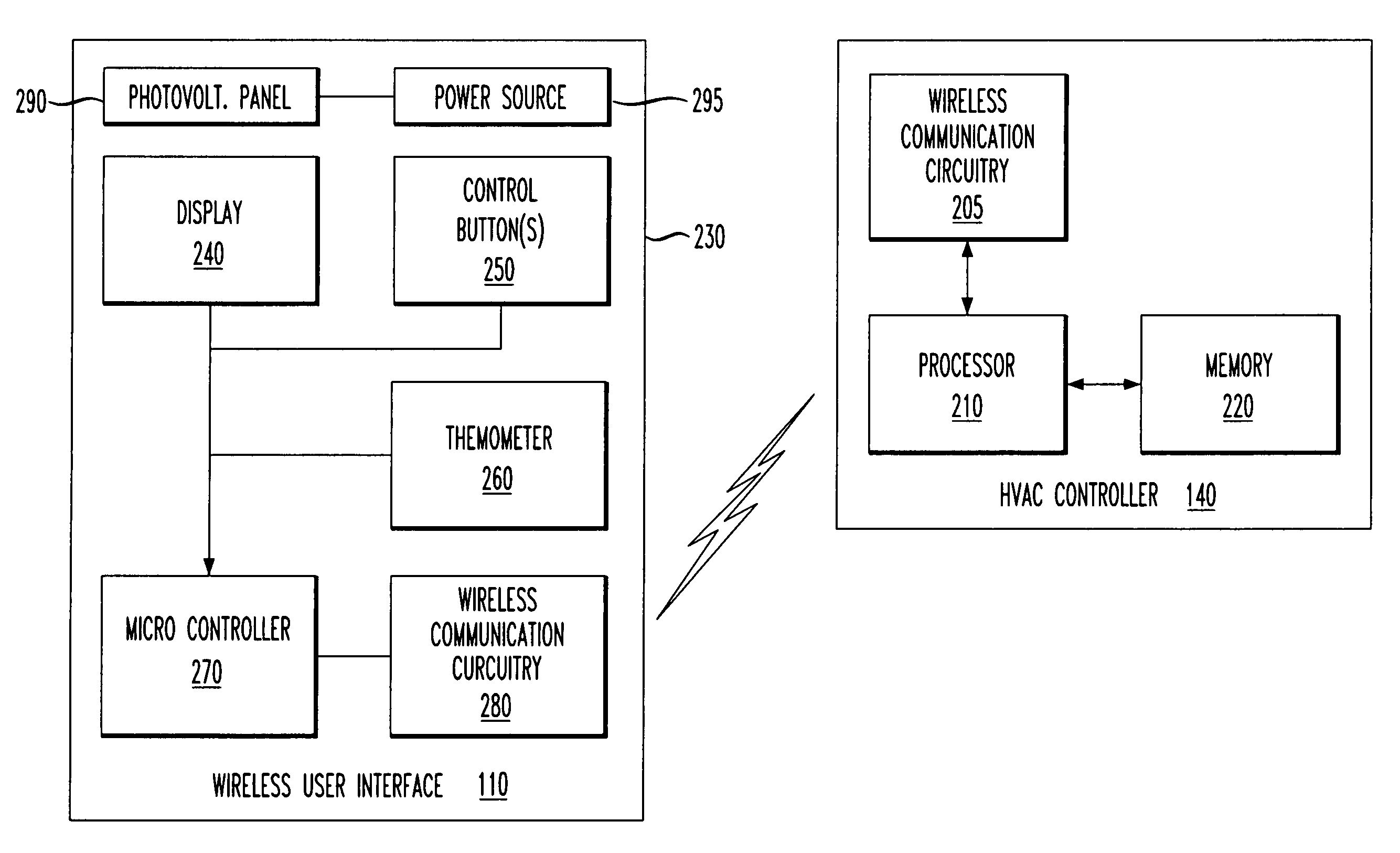
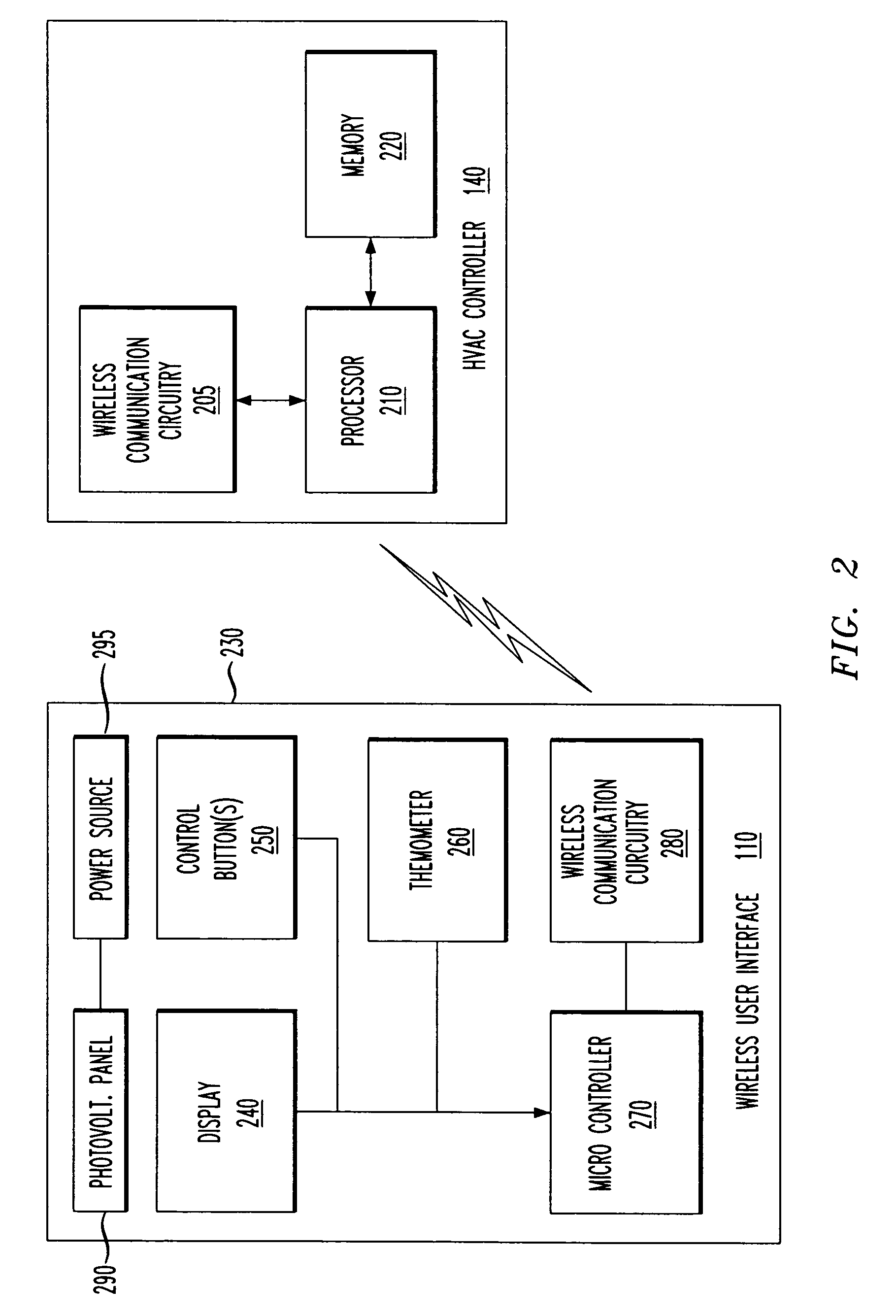
[0019]The HVAC system is illustrated as having a plurality of wireless user interfaces 110, 120, 130. The wireless user interfaces 110, 120, 130 may correspond to different zones of heating, ventilation and cooling in the HVAC system or may belong to a single zone. Though not separately referenced in FIG. 1, each wireless user interface 110, 120, 130 has a chassis that, in turn, has a display and at least one control button. Though not visible in FIG. 1, each wireless user interface 110, 120, 130 contains a temperature sensor, wireless communication circuitry and a microcontroller, which is a relatively low power processor of relatively limited capability.

[0020]The HVAC system further includes an HVAC controller 140. The HVAC controller 140 is wireless...


PUM


Abstract

A wireless user interface for an HVAC controller, a method of operating a wireless user interface for an HVAC controller and an HVAC system incorporating the wireless user interface or the method. In one embodiment, the wireless user interface includes: (1) a chassis having a display and at least one control button and containing a temperature sensor and wireless communication circuitry and (2) a microcontroller configured to cause the wireless communication circuitry to generate outbound data packets for wireless transmission to the HVAC controller containing temperature readings from the temperature sensor and when the at least one control button is pressed and receive inbound data packets from the HVAC controller that determine a content of the display.

Description

TECHNICAL FIELD OF THE INVENTION[0001]The present invention is directed, in general, to heating / ventilation / air conditioning (HVAC) systems and, more specifically, to a wireless user interface for an HVAC controller and a method of operating the interface.BACKGROUND OF THE INVENTION[0002]Control of central HVAC systems has long been a topic of innovation. Early HVAC systems had only the most rudimentary control: a manual on / off switch. Later systems were fitted with a bimetal thermostat, which afforded them automatic, temperature-dependent control.[0003]Today's thermostats do much more than simply instruct the HVAC system to turn on or off. They allow a user to set the mode of the HVAC system (e.g., heating, cooling or ventilation). They can provide zones of separate thermostatic control. More sophisticated electronic thermostats typically provide setback, which allows setpoint temperatures to vary depending upon time of day or day of week. Some electronic thermostats can give tempe...

Claims


Application Information

Patent Timeline
Patent Type & Authority Patents(United States)
IPC IPC(8): G05D23/00G01M1/38B60H1/00
CPCG05D23/1905B60H1/00657F24F11/006F24F2011/0068F24F11/30F24F11/62F24F11/56F24F11/58F24F11/63F24F11/52
Inventor USELTON, ROBERT B.
Owner LENNOX IND
Why Eureka
Try Eureka