Cutting tool and cutting insert therefor

a cutting tool and cutting insert technology, applied in the direction of cutting inserts, manufacturing tools, shaping cutters, etc., can solve the problems of grooving tools but also non-face grooving tools, lateral instability of cutting inserts, and weakening of cutting structur

Active Publication Date: 2013-02-19
ISCAR LTD
View PDF14 Cites 8 Cited by
  • Summary
  • Abstract
  • Description
  • Claims
  • Application Information

AI Technical Summary

Problems solved by technology

The slot is open on each side of the cutting insert which not only weakens the structure of the cutting tool in the region of the slot and but also means that there is no natural retention of the cutting insert in the lateral direction leading to lateral instability of the cutting insert during metal cutting operations.
Clearly, this is a problem not only with face grooving tools but also with non-face grooving tools.
However, a disadvantage of convex-concave mating surfaces in the clamping region, when they are applied to both the upper and lower surfaces of the clamping portion of an insert is that it restricts the minimum size of the cutting insert thereby restricting the minimum groove diameter size that can be achieved.

Method used


Image

  • Cutting tool and cutting insert therefor
  • Cutting tool and cutting insert therefor
  • Cutting tool and cutting insert therefor

Examples


Embodiment Construction

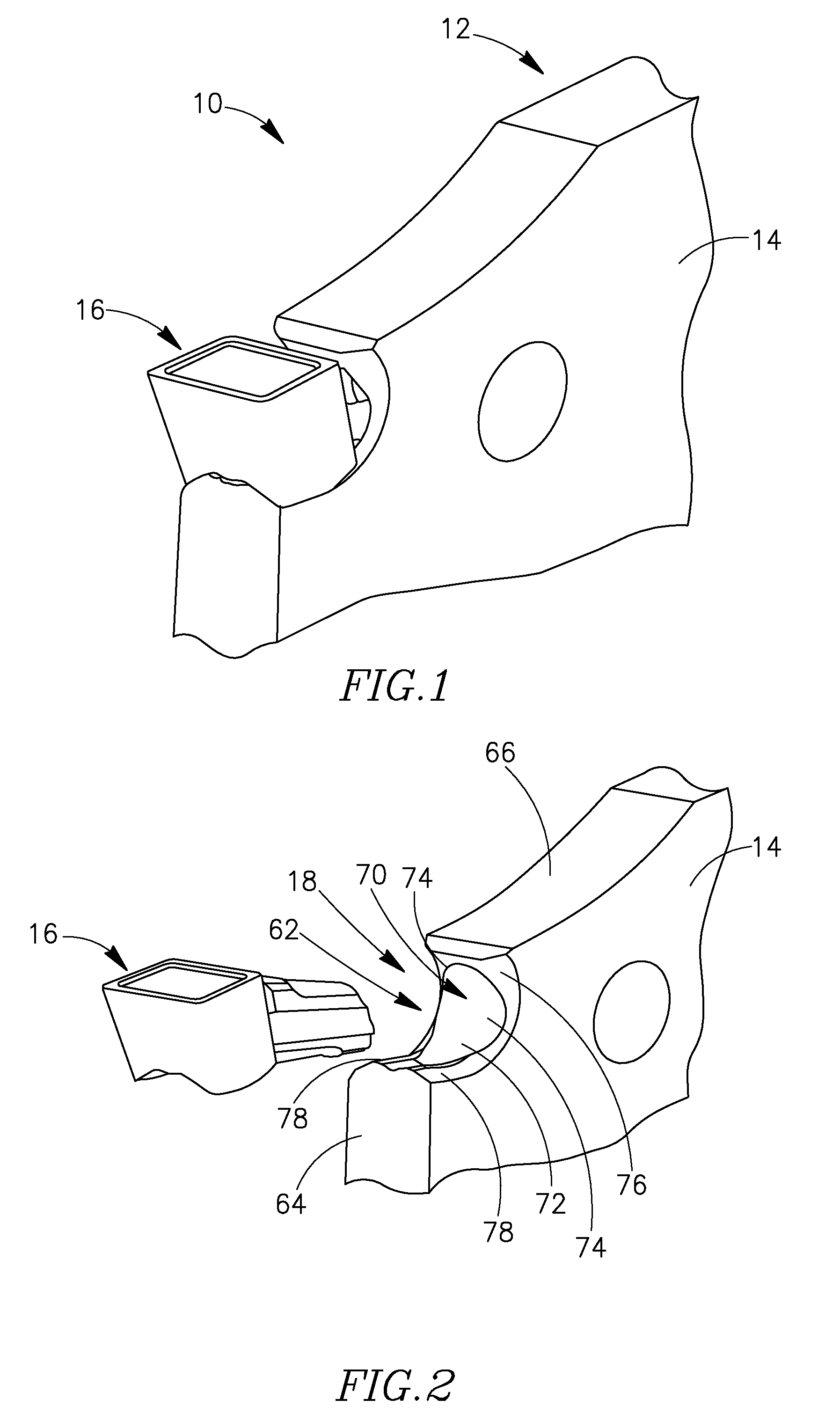
[0030]Attention is first drawn to FIGS. 1 and 2 showing a cutting section 10 of a cutting tool 12 in accordance with embodiments of the invention. The cutting tool 12 includes an insert holder 14 and a cutting insert 16 with the cutting insert 16 secured in an insert pocket 18 of the insert holder 14 in FIG. 1 and with the cutting insert 16 removed from the insert pocket 18 in FIG. 2.

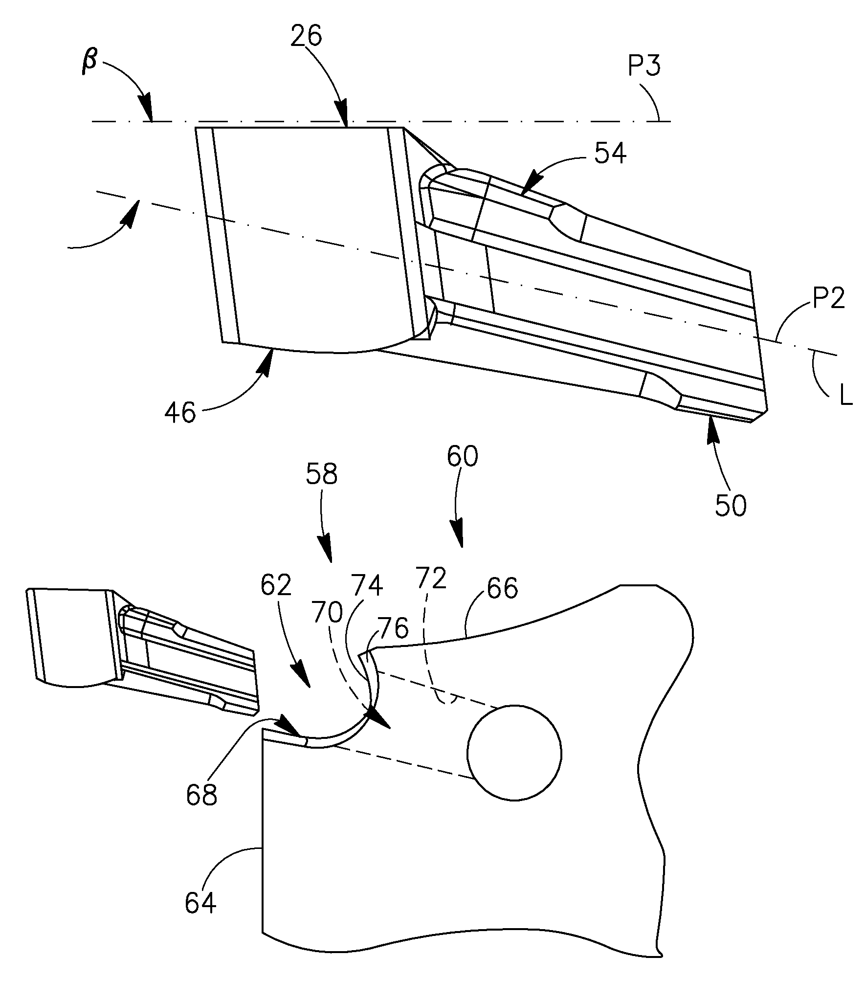
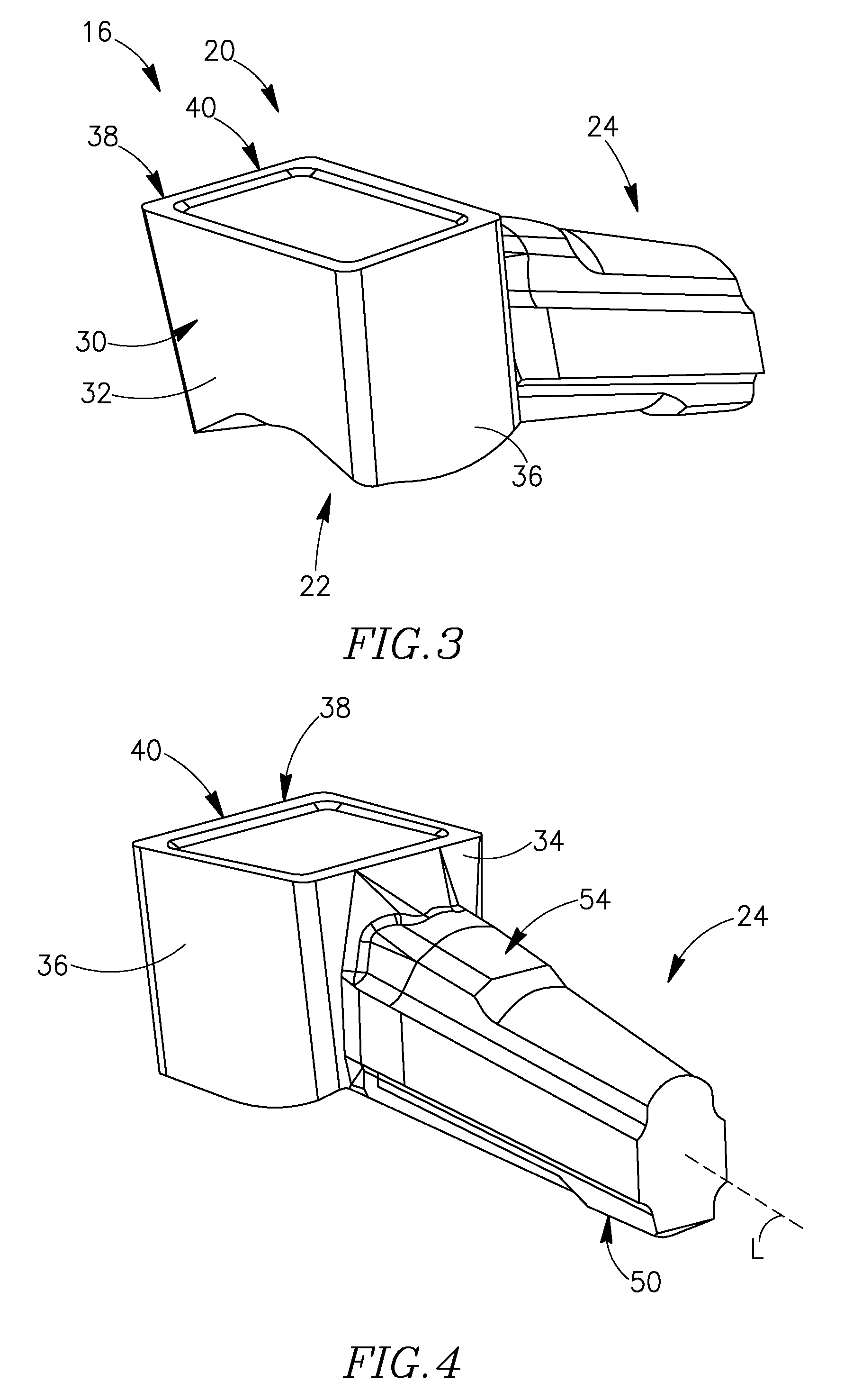
[0031]The cutting insert 16 is shown in detail in FIGS. 3 to 8. The cutting insert 16 has a cutting portion 20 at a forward end 22 of the cutting insert 16 and an elongated locating portion 24 extending rearwardly from the cutting portion 20. The cutting insert 16 is preferably, but not necessarily, made of cemented carbide such as, for example, tungsten carbide. The cutting insert 16 may be made by a pressing, or injection molding, and sintering process. The cutting insert 16 may also be ground. The elongated locating portion 24 has a longitudinal axis L defined at the intersection of two planes, a lon...


PUM

PropertyMeasurementUnit
abutment angleaaaaaaaaaa
symmetryaaaaaaaaaa
shapeaaaaaaaaaa

Abstract

A cutting tool has a cutting insert releasably retained in an insert pocket. The insert pocket includes a supporting portion having support surfaces and a clamping portion including a socket having a socket wall, the socket extending rearwardly from the supporting portion. The cutting insert has a cutting portion with front abutment surfaces and an elongated locating portion extending rearwardly from the cutting portion. The cutting insert is retained in the insert pocket with the front abutment surfaces abutting the support surfaces and with the locating portion located in the socket with abutment surfaces of the locating portion in abutment with the socket wall.

Description

FIELD OF THE INVENTION[0001]This invention relates to a cutting insert and to a cutting tool particularly, but not exclusively, for grooving, turning, parting, and face grooving.BACKGROUND OF THE INVENTION[0002]A typical prior art face grooving tool is shown, for example, in FIG. 2 of U.S. Pat. No. 5,709,508, in which a cutting insert is retained in a slot formed between an upper clamping jaw and a curved lower base jaw. The slot is open on each side of the cutting insert which not only weakens the structure of the cutting tool in the region of the slot and but also means that there is no natural retention of the cutting insert in the lateral direction leading to lateral instability of the cutting insert during metal cutting operations. Clearly, this is a problem not only with face grooving tools but also with non-face grooving tools. In order to stabilize the cutting insert against lateral forces, the jaws of the tool and the upper and lower surfaces of the cutting insert can be pr...

Claims


Application Information

Patent Timeline
Patent Type & Authority Patents(United States)
IPC IPC(8): B23B27/00B23B27/04
CPCB23B27/045B23B29/043B23B2240/32Y10T407/2272Y10T407/2282Y10T407/2288Y10T407/2268Y10T407/24B23B27/04B23B27/16B23B29/04B23B2200/08
Inventor HECHT
Owner ISCAR LTD
Why Eureka
Try Eureka