Torque limiter

a limiter and torque technology, applied in the field of torque limiters, can solve the problems of changing the properties of instruments, the maximum torque is determined by the elastic body, etc., and achieve the effect of convenient completely sterilization

Active Publication Date: 2013-02-19
WS SOLUTIONS
View PDF21 Cites 2 Cited by
  • Summary
  • Abstract
  • Description
  • Claims
  • Application Information

AI Technical Summary

Benefits of technology

[0004]An object of the invention is to eliminate, or at least mitigate, the disadvantages of the prior art described above and provide an improved torque limiter, a method for producing an improved torque limiter and an assembly kit for an improved torque limiter. In particular, an object of the invention is to develop a torque limiter or a corresponding assembly kit which can be adapted to different maximum torques to be transmitted and which exhibit reduced changing of the mechanical properties over time.
[0005]A torque limiter, particularly for surgical instruments, a method for producing a corresponding torque limiter and an assembly kit for a torque limiter are provided to achieve the object. By providing an inclined plane as a guide for a rolling body, a certain resistance to displacements of the rolling body along the oblique plane can be achieved by choosing the angular position of the inclination. Furthermore, a maximum transmissible torque can be chosen or set by choosing the number of rolling bodies held in the cage. In this way, a maximum transmissible torque can be chosen by simple means. It should be noted that, opposite the side wall that is arranged at an oblique angle to a circumferential direction of the cage, there is preferably arranged a second side wall, which is parallel to this first side wall and together with the first side wall forms the rolling body holder. This achieves the effect that, depending on the direction of rotation of the cage in relation to the rotor, a displacement of the rolling body in the rolling body holder is opposed with a different resistance, since the equilibrium of forces at the point of contact of the rolling body on the side wall differs according to the direction of rotation. The consequence is that a maximum transmissible torque can be transmitted in one direction and a virtually unlimited torque, or at least a torque that is increased significantly in comparison with the above-named maximum torque, can be transmitted in the other direction. This achieves the effect that a seized screw can in any event be loosened.

Problems solved by technology

It is disadvantageous, however, that the maximum torque is determined by the elastic body.
Furthermore, fatigue of the synthetic materials of the elastic body may bring about a change in the properties of the instrument.
This is disadvantageous, since the maximum transmissible torque can change.

Method used


Image

  • Torque limiter
  • Torque limiter
  • Torque limiter

Examples


Embodiment Construction

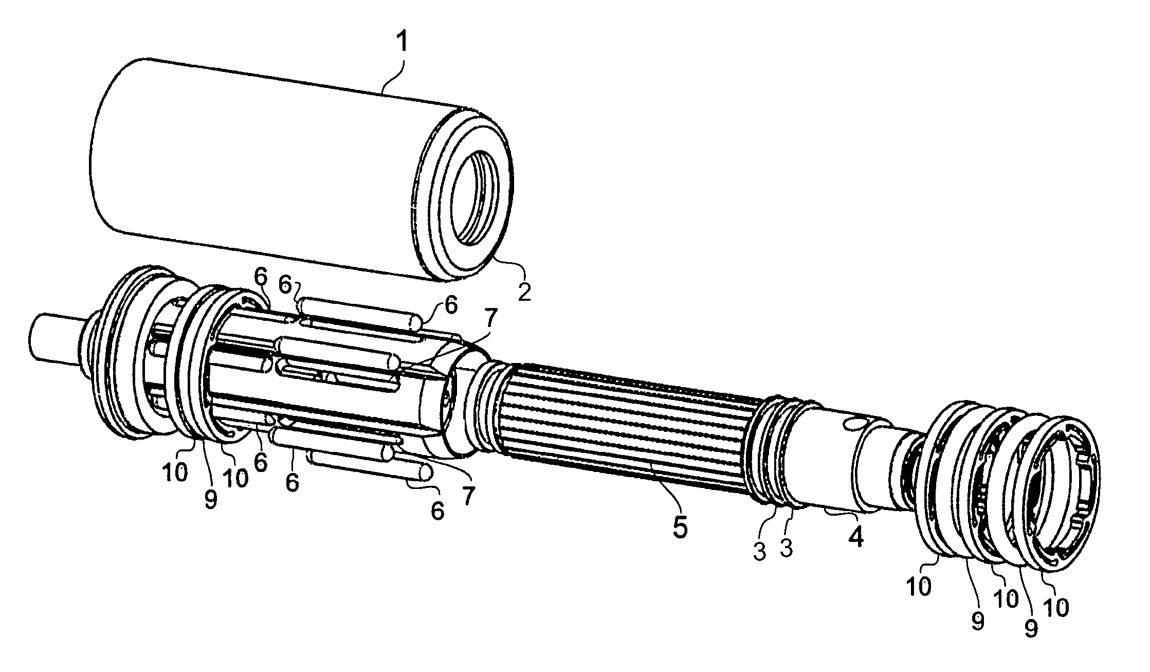
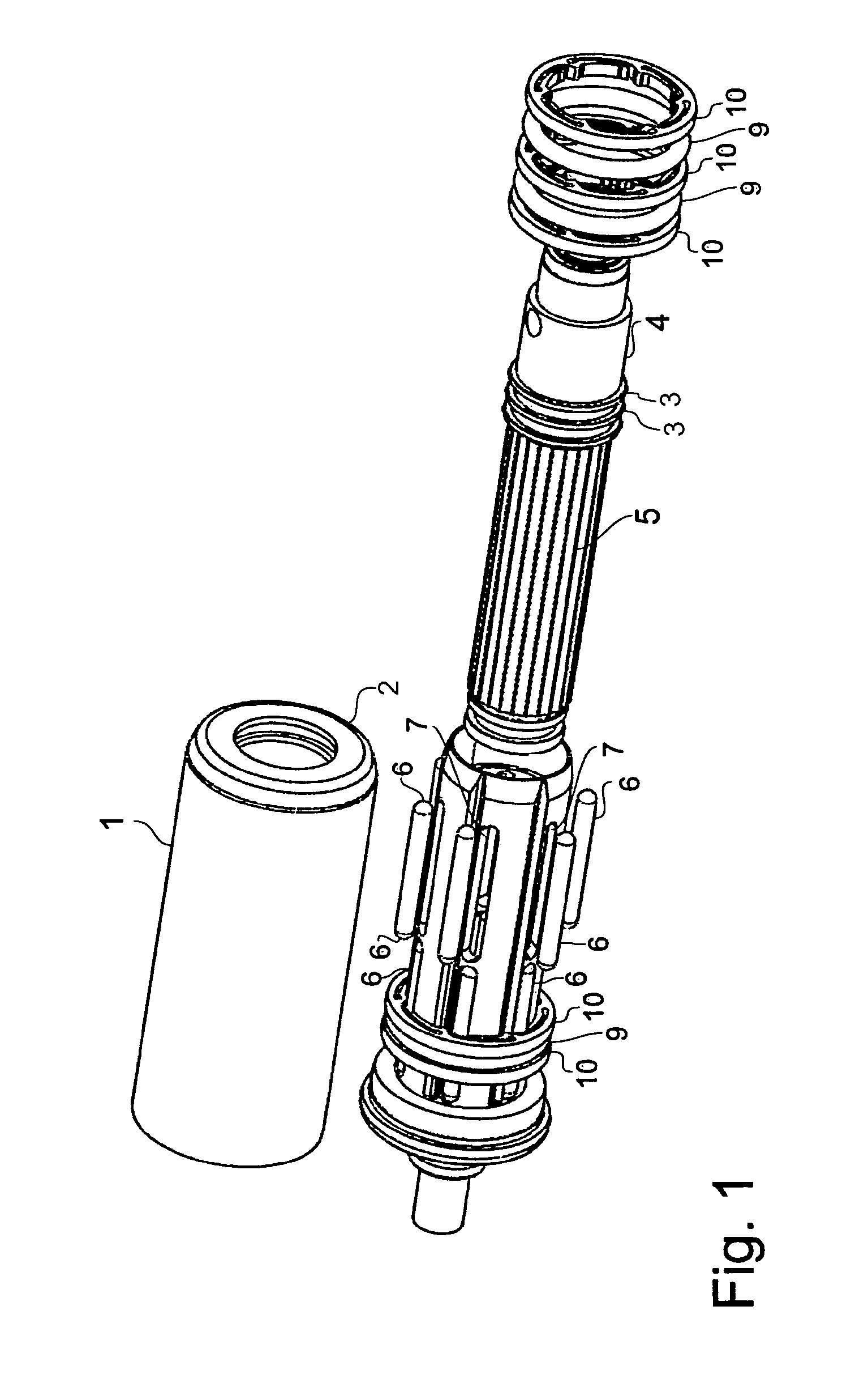
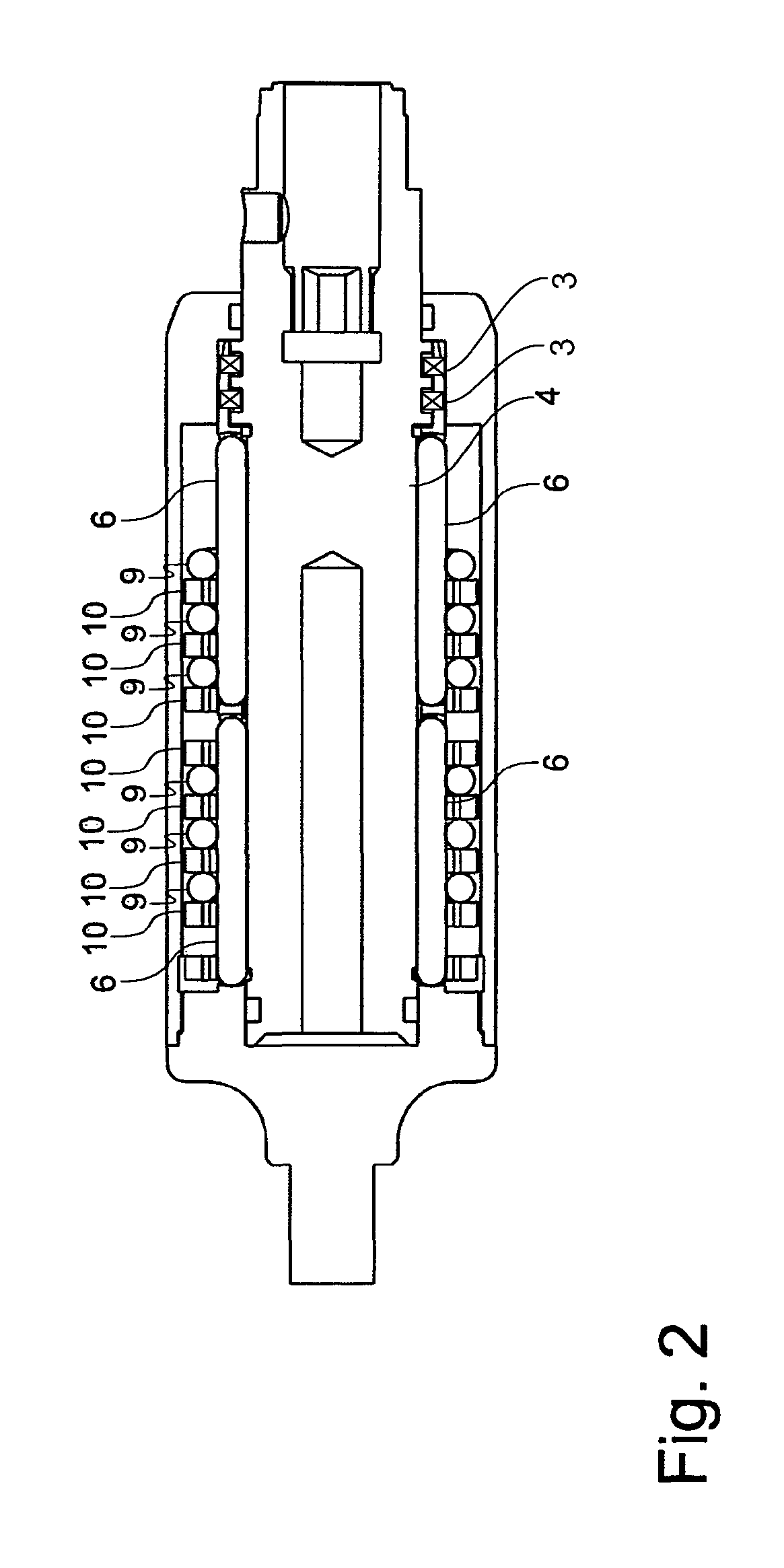
[0022]FIG. 1 perspectively shows in a schematic exploded representation a torque limiter according to the invention or an assembly kit according to the invention for a torque limiter. The torque limiter has an outer protective sleeve 1, a covering cap 2 and a number of bearings, of which at least one bearing 3 is shown in FIG. 1. The drive output shaft of the torque limiter is formed integrally by an inner rotor 4, on the outer side of which longitudinal grooves are arranged as depressions 5. The longitudinal grooves as depressions 5 are provided for the purpose of interacting with rolling bodies 6, the inner radius of the longitudinal grooves corresponding to the outer radius of the rolling bodies 6. Rollers rounded at the ends are provided as rolling bodies 6. In the case of other typical embodiments, rollers that have sharp-edged ends are provided. The rolling bodies 6 are held in rolling body holders 7 of a cage 8. The cage 8 at the same time forms a drive input shaft of the tor...


PUM


Abstract

A torque limiter, in particular for a surgical instrument, comprises a rotor (4) and a cage (8) arranged coaxially in relation to the rotor (4), the cage has at least one rolling body holder (7) with a rolling body (6) held in it, the rolling body holder (7) has at least one side wall which is arranged at an oblique angle relative to a circumferential direction of the cage (8).

Description

FIELD OF THE INVENTION[0001]The invention relates to a torque limiter, in particular for a surgical instrument, a method for producing the torque limiter and an assembly kit for the torque limiter.BACKGROUND OF THE INVENTION[0002]In surgery, screws or other components often have to be tightened with a defined torque. In such cases, a maximum torque in the direction of the tightening of the screw must not be exceeded in order to avoid damage to the components or to bones. On the other hand, loosening of the screw should be possible, including with a higher torque, in order for it to be possible in the event of a seized screw to remove it again from the body. For this reason, torque limiters such as are used in surgery are fundamentally different from torque limiters such as are used generally in mechanics, since in the case of the latter a freewheel is usually arranged in the opposite direction.[0003]There are torque limiters known from the prior art that operate with an elastic body...

Claims


Application Information

Patent Timeline
Patent Type & Authority Patents(United States)
IPC IPC(8): F16D7/10
CPCA61B17/1631A61B17/8875B25B23/141B25B23/1427A61B17/1624A61B2019/301A61B2090/031
Inventor WERNZ, ULRICHSIEBOLD, STEPHAN
Owner WS SOLUTIONS
Why Eureka
Try Eureka