

Automatic transmission
a transmission and automatic technology, applied in the direction of mechanical equipment, transportation and packaging, gearing, etc., can solve the problems of more frictional losses and frictional loss
- Summary
- Abstract
- Description
- Claims
- Application Information
AI Technical Summary
Benefits of technology
Problems solved by technology
Method used
Image

Examples
first embodiment
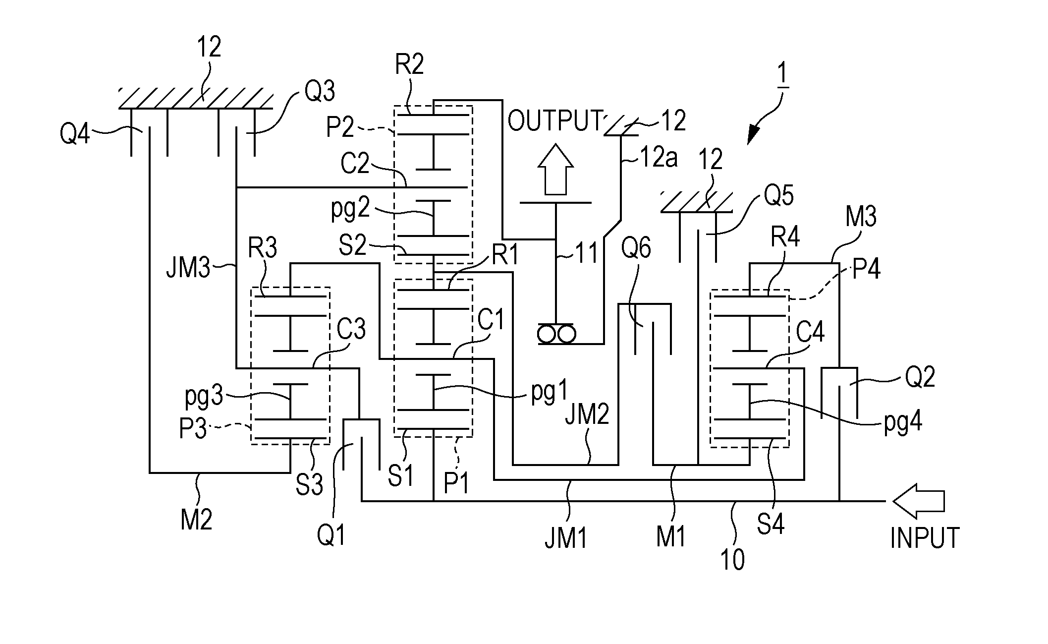
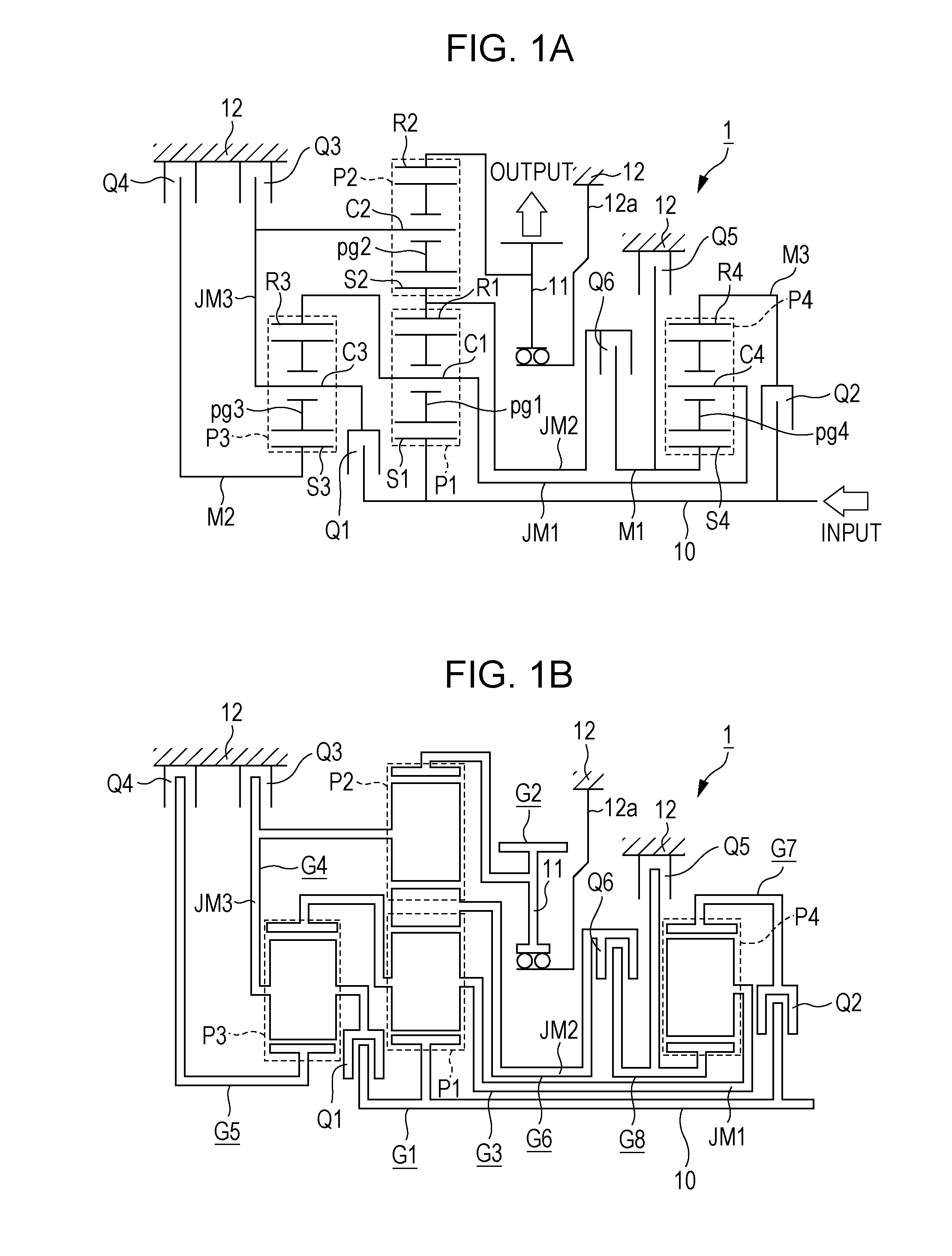
[0021]FIG. 1A is a skeleton diagram of an automatic transmission 1 according to a first embodiment. The automatic transmission 1 includes an input shaft 10 and an output member 11. The input shaft 10 is rotatably and pivotally supported in a casing member 12 that constitutes a transmission case of the automatic transmission 1. The output member 11 is supported by a support member 12a so as to rotate coaxially with the input shaft 10. The support member 12a is supported by the casing member 12.
[0022]The input shaft 10 receives power input from a driving source (not illustrated) such as an internal combustion engine or a motor and is thus rotated by the power. A starting device may be provided between the input shaft 10 and the driving source. Providing the starting device brings about an effect of lessening a gear change shock. Examples of a starting device include a clutch-type starting device (such as a single-plate clutch or a multiplate clutch) and a hydraulic coupling starting d...
second embodiment
[0046]Although the first to sixth engagement assemblies Q1 to Q6 are described as being frictional engagement assemblies in the first embodiment, meshing-type engagement assemblies such as dog clutches / brakes may also be employed.
[0047]Compared with a frictional engagement assembly, a meshing-type engagement assembly substantially causes no frictional losses due to drag when disengaged. The meshing-type engagement assembly can also transmit a large amount of torque. On the other hand, the meshing-type engagement assembly causes a stronger gear change shock. For lessening the gear change shock, complex control or a longer time for changing from the disengaged state to the engaged state is required. For this reason, it is preferable that either the frictional engagement assembly or the meshing-type engagement assembly be used in accordance with the location.
[0048]FIG. 5A is a skeleton diagram of an automatic transmission 2 according to a second embodiment. The structure of the automat...
third embodiment
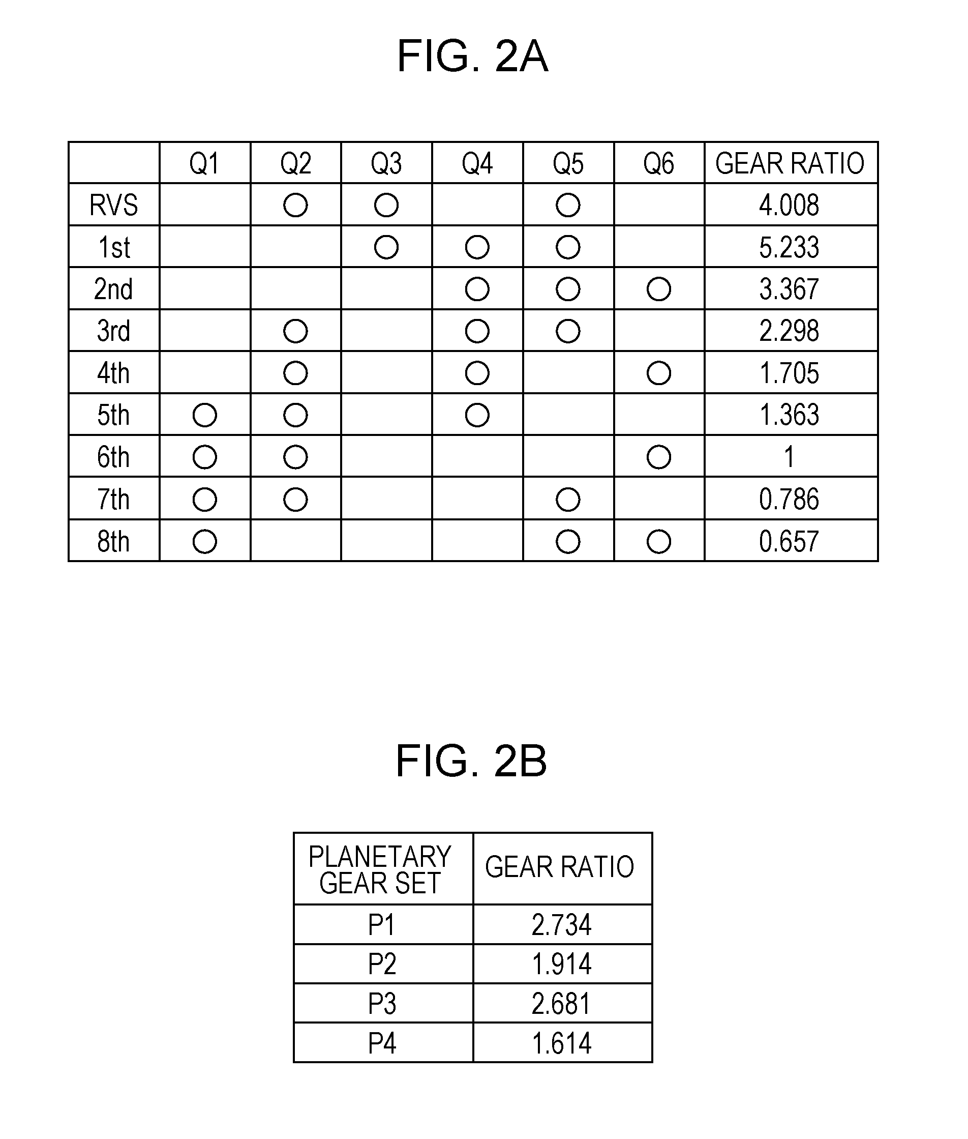
[0052]Since dog brakes are employed as the third and fourth engagement assemblies Q3′ and Q4′ in the second embodiment, a gear change shock caused during a gear change from the neutral gear to the first gear speed may become larger. More specifically, when a torque converter or the like is used as a starting device, the input shaft 10 is also rotating at the neutral gear, and thus the groups G4 and G5 illustrated in FIG. 1B also rotate, to which the third and fourth engagement assemblies Q3′ and Q4′ are supposed to be engaged, respectively. For this reason, when the third and fourth engagement assemblies Q3′ and Q4′ are engaged according to the engagement chart shown in FIG. 2A or 4, the engagements are not performed smoothly and a large gear change shock may occur during a gear change from the neutral gear to the first gear speed. To address this situation, another engagement assembly may be additionally provided.
[0053]FIG. 5B is a skeleton diagram of an automatic transmission 3 ac...
PUM
 Abstract
Description
Claims
Application Information