System and method for 3D object recognition

a technology of object recognition and system, applied in the field of machine vision systems, can solve the problems of occluded and perspectively distorted features, complex object recognition task, and robustly finding features, and achieve the effect of small focal length, stronger perspective distortion in the image, and bigger object depth

Active Publication Date: 2013-02-19
MVTEC SOFTWARE
View PDF20 Cites 61 Cited by
  • Summary
  • Abstract
  • Description
  • Claims
  • Application Information

AI Technical Summary

Benefits of technology

[0012]This invention provides a system and method for recognizing a 3D object in a single camera image and for determining the 3D pose of the object with respect to the camera coordinate system. The invention provides methods that substantially eliminate many of the prior-art problems of view-based object recognition methods just described.

Problems solved by technology

This complicates the object recognition task dramatically because the relative movement between camera and object results in different perspectives that cannot be expressed by 2D transformations.
Several drawbacks are associated with these approaches: In general, it is difficult to robustly find the features in the image because of changing viewpoints, which results in occluded and perspectively distorted features.
Template matching methods cannot cope with this kind of distortions.
Consequently, these approaches are only suited for a very limited range of viewpoint changes.
In addition, marker-based approaches are not flexible with regard to changing objects.
It is often difficult to add the markers and to measure their 3D coordinates.
Furthermore, many objects are not suited for adding markers to their surface.
Because no information about the size of the object is used, the pose of the object cannot be determined with this approach.
Naturally, these kinds of feature-based approaches are not flexible with regard to changing objects.
In general, feature-based recognition techniques suffer from the fact that the extraction of the features cannot be carried out robustly with respect to clutter and occlusions.
Furthermore, the correct assignment of the extracted 2D features to the 3D features is a NP complete combinatorial problem, which makes these techniques not suited for industrial applications, where a fast recognition is essential.
Unfortunately, the acquisition of the training images and their comparison with the 2D search image is very costly because of the very large number of training images that are necessary to cover a reasonably large range of allowed viewpoints.
These problems make this approach not suited for industrial applications.
Again, there is the problem of the very large number of 2D projections that is necessary to cover a reasonably large range of allowed viewpoints.
But even then, the number of 2D projections that must be compared with the 2D search image remains too large, so that these view-based recognition techniques are not suited for industrial applications.
Often the number of views is reduced by creating the views such that the camera is always directed to the center of the 3D object, but then, objects appearing not in the center of the image cannot be found because of the resulting projective distortions.
Another unsolved problem of these view-based recognition techniques is the creation of the 2D projections such that they are suitable for the comparison with the 2D search image.
Unfortunately, this kind of approaches strongly relies on a distinct texture on the object's surface, and hence is not suitable for most industrial applications.
Approaches that use only a wireframe projection of the 3D model face the problem that many of the projected edges are not visible in the search image, especially on slightly curved surfaces, which are typically approximated by planar triangles in the 3D model of the object.
Often, the techniques that are used for the comparison of the 2D projections with the 2D search image are not robust against clutter and occlusions (Ulrich, 2003).
Finally, the accuracy of the object pose determined by pure view-based approaches is limited to the distance with which the allowed range of viewpoints is sampled.

Method used


Image

  • System and method for 3D object recognition
  • System and method for 3D object recognition
  • System and method for 3D object recognition

Examples


Embodiment Construction

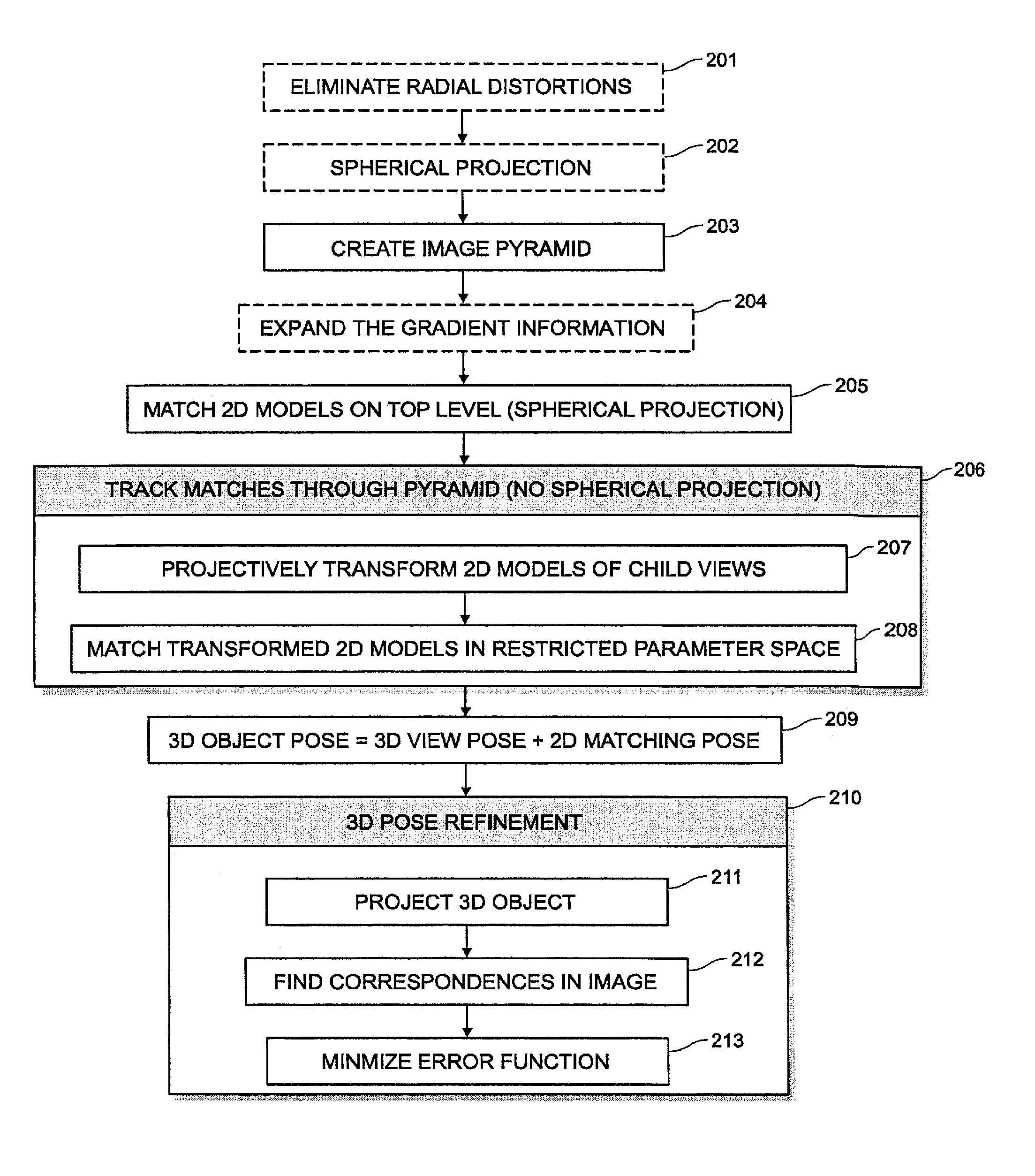
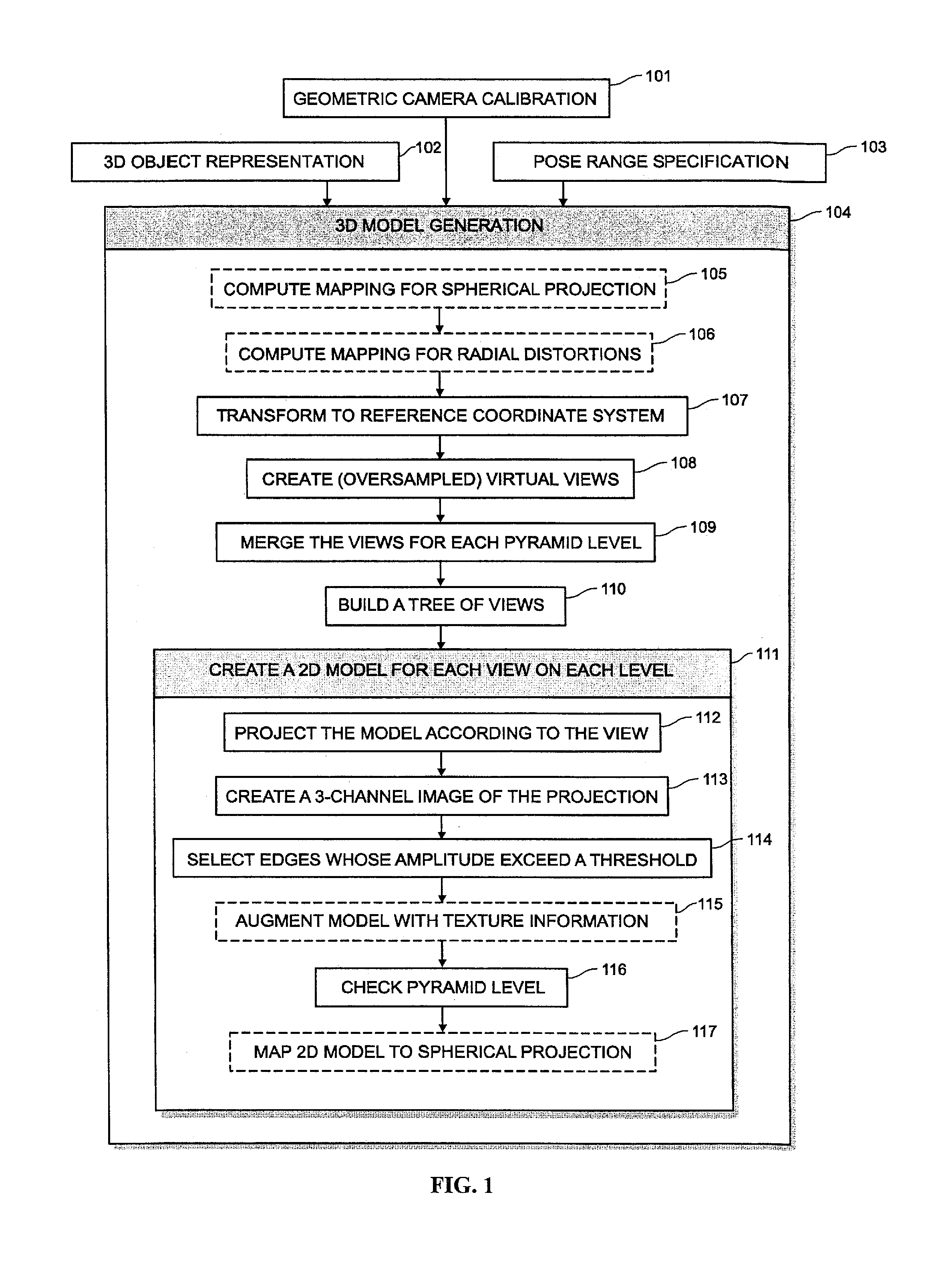
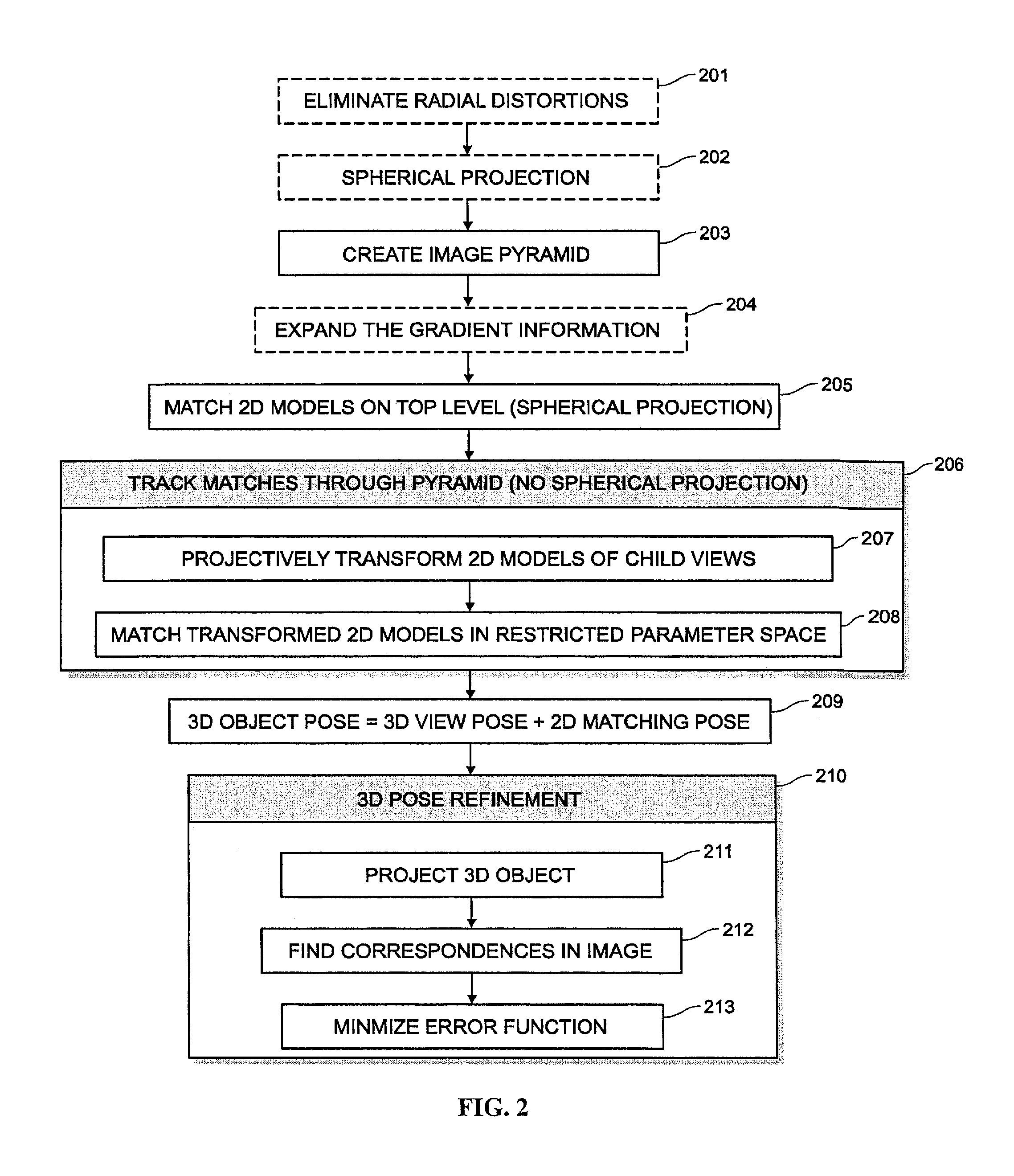
[0058]In the following, the single steps of the present invention are described in detail. First, the geometric camera calibration that is the initial step to obtain a high accuracy. After that, some information is given of how the 3D object should be represented. In the next section, the generation of the 3D model that can be used to find the 3D object in a search image is explained. The 3D model generation will be denoted as offline-phase in the remainder of the description. Then, methods are described that can be used to recognize the object in an image. This step will be denoted as online-phase in the remainder of the description. The described steps of the offline-phase are summarized in the flow chart of FIG. 1, the described steps of the online-phase are summarized in the flow chart of FIG. 2. In both flow charts, essential steps are indicated by a solid box, whereas optional steps are indicated by a dashed box. Finally, a robot vision system is introduced that makes use of t...


PUM


Abstract

The present invention provides a system and method for recognizing a 3D object in a single camera image and for determining the 3D pose of the object with respect to the camera coordinate system. In one typical application, the 3D pose is used to make a robot pick up the object. A view-based approach is presented that does not show the drawbacks of previous methods because it is robust to image noise, object occlusions, clutter, and contrast changes. Furthermore, the 3D pose is determined with a high accuracy. Finally, the presented method allows the recognition of the 3D object as well as the determination of its 3D pose in a very short computation time, making it also suitable for real-time applications. These improvements are achieved by the methods disclosed herein.

Description

FIELD OF THE INVENTION[0001]This invention relates generally to machine vision systems, and more particularly, to visual recognition of 3D objects in an image as well as to determination of their 3D pose.BACKGROUND OF THE INVENTION[0002]Object recognition is part of many computer vision applications. In some cases, the object is assumed to be planar and the transformation of the object in the image is limited to a certain degree, for example, to similarity transformations or projective transformations. There is a multitude of matching approaches of various types available in literature that are already able to solve this task. A survey of matching approaches is given by Brown (1992). In most cases, the model of the object is generated from an image of the object. Two examples for such approaches that fulfill the requirements for industrial applications, i.e., fast computation, high accuracy, robustness to noise, object occlusions, clutter, and contrast changes are presented in EP 1,...

Claims


Application Information

Patent Timeline
Patent Type & Authority Patents(United States)
IPC IPC(8): G06T15/00
CPCB25J9/1692G06V20/64G06V30/2504G06V30/1914G06F18/28
Inventor WIEDEMANN, CHRISTIANULRICH, MARKUSSTEGER, CARSTEN
Owner MVTEC SOFTWARE
Why Eureka
Try Eureka