Robot

Active Publication Date: 2013-02-19
HONDA MOTOR CO LTD
View PDF17 Cites 27 Cited by
  • Summary
  • Abstract
  • Description
  • Claims
  • Application Information

AI Technical Summary

Benefits of technology

[0008]The present invention has been accomplished in view of the aforementioned problems, and it is therefore an object of the present invention to provide a robot capable of appropriately adjusting a position and the like of a main body in view of executing a specified task involving an interaction with a target object.
[0013]According to the robot of the second aspect of the present invention, the position and the posture of the main body are being controlled according to the first target path, the robot moves from the second specified area to the first specified area. Thereafter, with the position and the posture of the main body being controlled according to the corrected second target path, the robot moves back to the second specified area again and stands there. In other words, the robot returns back to the first specified area from the second specified area where the robot is standing and then moves back to the second specified area again and stands in the second specified area. Thereby, the position and the like of the main body can be adjusted appropriately from the viewpoint of making the robot execute the specified task.
[0017]According to the robot of the fourth aspect of the present invention, when the first position / posture condition has been satisfied, the robot moves from the first specified area to the second specified area with the position and the posture of the main body being controlled according to the second target path. Thereby, the target position and the target posture of the main body at the starting point of the second target path, namely, the target position and the target posture of the main body when the robot is standing in the first specified area after the correction is adjusted identical to that before the correction roughly. Even though the position and the like of the main body when the robot is standing in the second specified area are inappropriate in the previous time from the viewpoint of executing the specified task, the position and the like of the main body in the current time can be adjusted appropriately.
[0019]According to the robot of the fifth aspect of the present invention, the current starting point of the second target path can be adjusted to satisfy the first position / posture condition by making the robot perform foot stepping in the first specified area. Thus, as mentioned above, the second target path is corrected, and the robot moves from the first specified area to the second specified area with the position and the posture of the main body being controlled according to the corrected second target path. Thereby, even though the position and the like of the main body when the robot is standing in the second specified area are inappropriate in the previous time from the viewpoint of executing the specified task, the position and the like of the main body in the current time can be adjusted appropriately.
[0021]According to the robot of the sixth aspect of the present invention, the position and the like of the main body can be adjusted appropriately; therefore, the robot can execute the task of connecting the second connector disposed with the charging unit to the first connector and charging the battery with the charging unit.
[0023]According to the robot of the seventh aspect of the present invention, the position and the like of the main body can be adjusted appropriately; therefore, the robot can execute the specified task of holding the target object with the hand or releasing the target object from the hand through moving the arms and the like.

Problems solved by technology

However, due to the reasons that the position or the posture or the position and the posture (hereinafter, referred to as position and the like where appropriate) of the second connector are deviated from the position where it should be, the interaction between the legs of the robot and the floor is different from what has been assumed or the like, despite that the robot is standing in the second specified area with a specified posture, it is possible that the position and the like of the first connector are inappropriate to be connected to the second connector.

Method used


Image

  • Robot
  • Robot
  • Robot

Examples


Embodiment Construction

[0040]Hereinafter, an embodiment of a robot according to the present invention will be described with reference to the drawings. Descriptions will be firstly given on a structure of the robot.

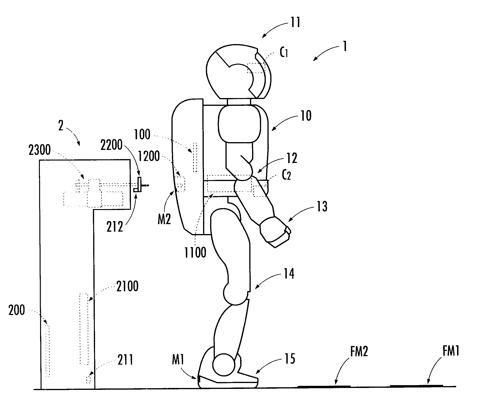
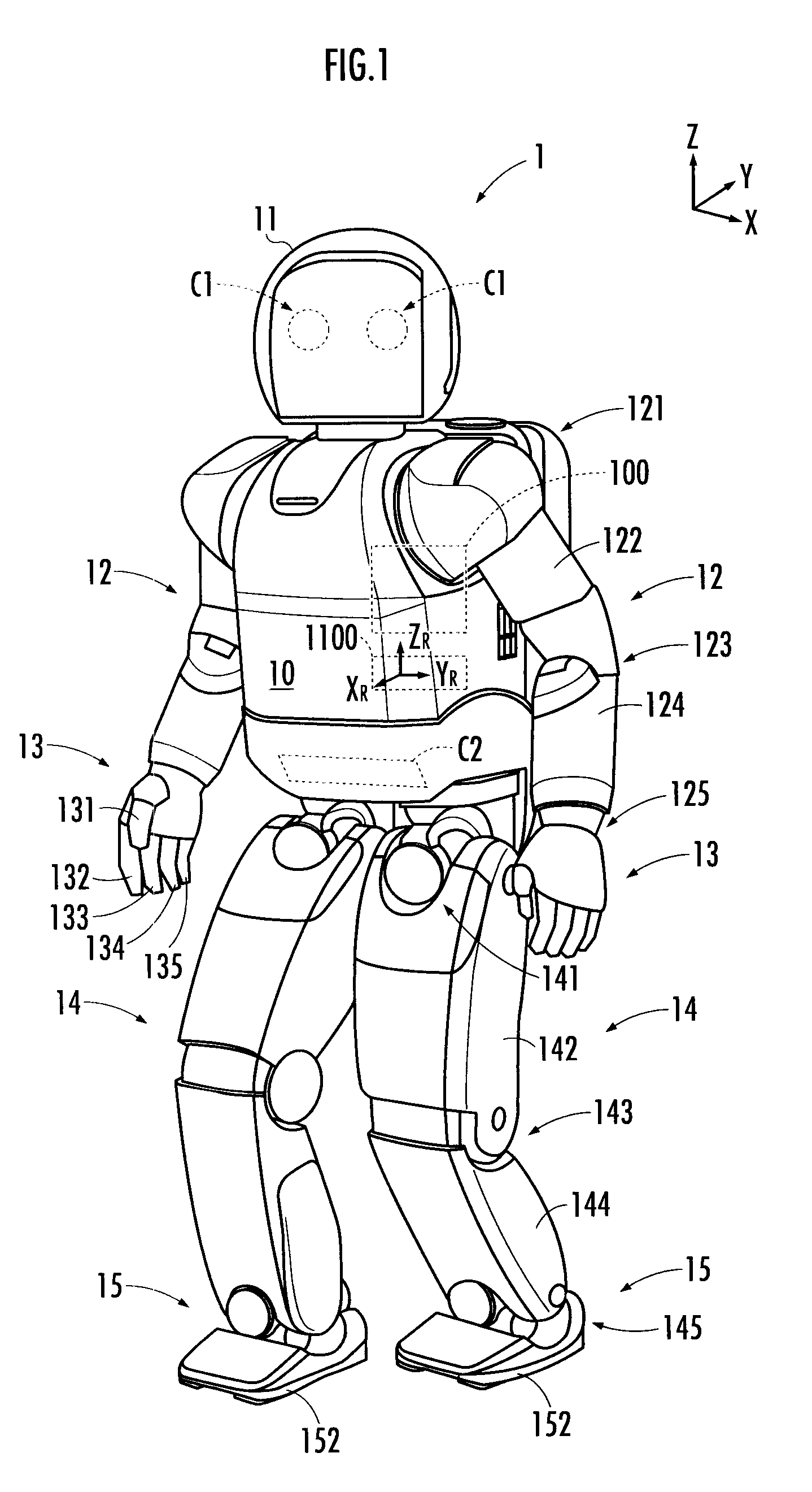
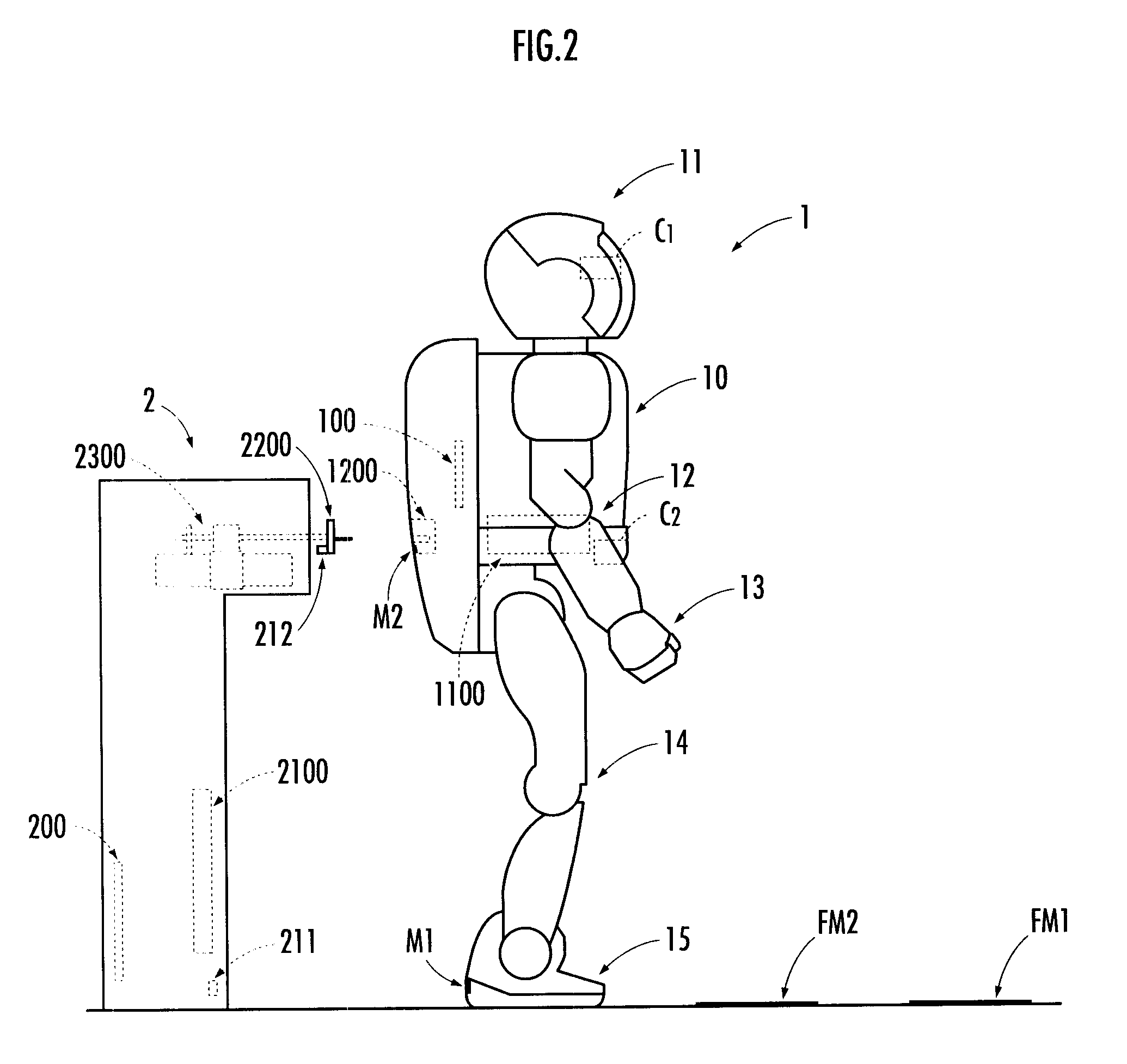
[0041]The robot 1 illustrated in FIG. 1 is a humanoid robot moving on legs. Similar to a human being, the robot 1 has a main body 10, a head 11 disposed at the upper end of the main body 10, right and left arms 12 which are provided at an upper portion of the main body 10 by extending from both sides thereof, respectively, right and left hands 13 provided at the respective end portion of the right and left arms 12, right and left legs 14 which are provided respectively at a lower portion of the main body 10 by extending downward thereof. The robot 1 is provided with a battery 1100 and a controller 100 configured to control the motions of the robot 1. It is acceptable that the controller 100 is a distributed control device composed of a main control unit and one or plural sub-control units which...


PUM

PropertyMeasurementUnit
movementaaaaaaaaaa
areaaaaaaaaaaa
azimuth angleaaaaaaaaaa

Abstract

Provided is a robot capable of appropriately adjusting a position and the like of a main body in view of executing a specified task involving an interaction with a target object. While the position and posture of the main body (10) are being controlled according to a second target path, the robot (1) moves from a first specified area to a second specified area and stands there. In this state, a second position deviation (=the deviation of the position of the main body from a second target path) and a second posture deviation (=the deviation of the posture of the main body from a second target posture) are determined. According to the determination result, the second target path is corrected so that the subsequent position deviation and the like may be smaller.

Description

PRIORITY CLAIM[0001]The present application is based on and claims the priority benefit of Japanese Patent Application 2008-005955 filed on Jan. 15, 2008, the contents of which are incorporated herein by reference in its entirety.BACKGROUND OF THE INVENTION[0002]1. Field of the Invention[0003]The present invention relates to a robot capable of moving autonomously according to motions of a plurality of legs extended from a main body thereof.[0004]2. Description of the Related Art[0005]There has been disclosed a technical art for charging a battery mounted in a robot capable of moving autonomously (refer to Japanese Patent Laid-open No. 2007-245332). According to the technical art, a first connector mounted in a main body of the robot and a second connector mounted with a charging unit are connected for certain according to the movement of the robot guided by a guiding member disposed in a charging station.[0006]Meanwhile, as a method of connecting the first connector with the second ...

Claims


Application Information

Patent Timeline
Patent Type & Authority Patents(United States)
IPC IPC(8): G06F19/00B25J5/00B25J9/10B25J13/08H01M50/247
CPCB25J19/005G05D1/0891H02J7/0045H01M10/42H01M10/46H01M2/1022Y02E60/10H01M50/247
Inventor NEKI, NORIOOKAZAKI, KOJINAKAYAMA, TAKASHIMUROMACHI, MASAAKIKANEKO, SATOSHIKIMURA, YUTA
Owner HONDA MOTOR CO LTD
Why Eureka
Try Eureka