AI technical title is built by Patsnap AI team. It summarizes the technical point description of the patent document.
a technology of a wedge blade and a spherical blade, which is applied in the field of wedge blades, can solve the problems of affecting the and the arrangement of the wedge blade on both parts is difficult, and achieves the effects of simple fitting, low material consumption, and high stability of the wedge blad
Active Publication Date: 2013-02-26
ROBERT BOSCH GMBH
View PDF35 Cites 25 Cited by
Summary
Abstract
Description
Claims
Application Information
AI Technical Summary
This helps you quickly interpret patents by identifying the three key elements:
Problems solved by technology
Method used
Benefits of technology
Benefits of technology
This configuration ensures a constant distance between spring rails, allowing for better curvature adaptation and increased stability, while reducing material usage and simplifying assembly, resulting in a secure and efficient wiper blade operation.
Problems solved by technology
However, if the form-fitting connection is subjected to heavy loading, it is expedient to arrange bumps on both parts.
Method used
Image
Click on the blue label to locate the original text in one second.
Reading with bidirectional positioning of images and text.
Examples
Embodiment Construction
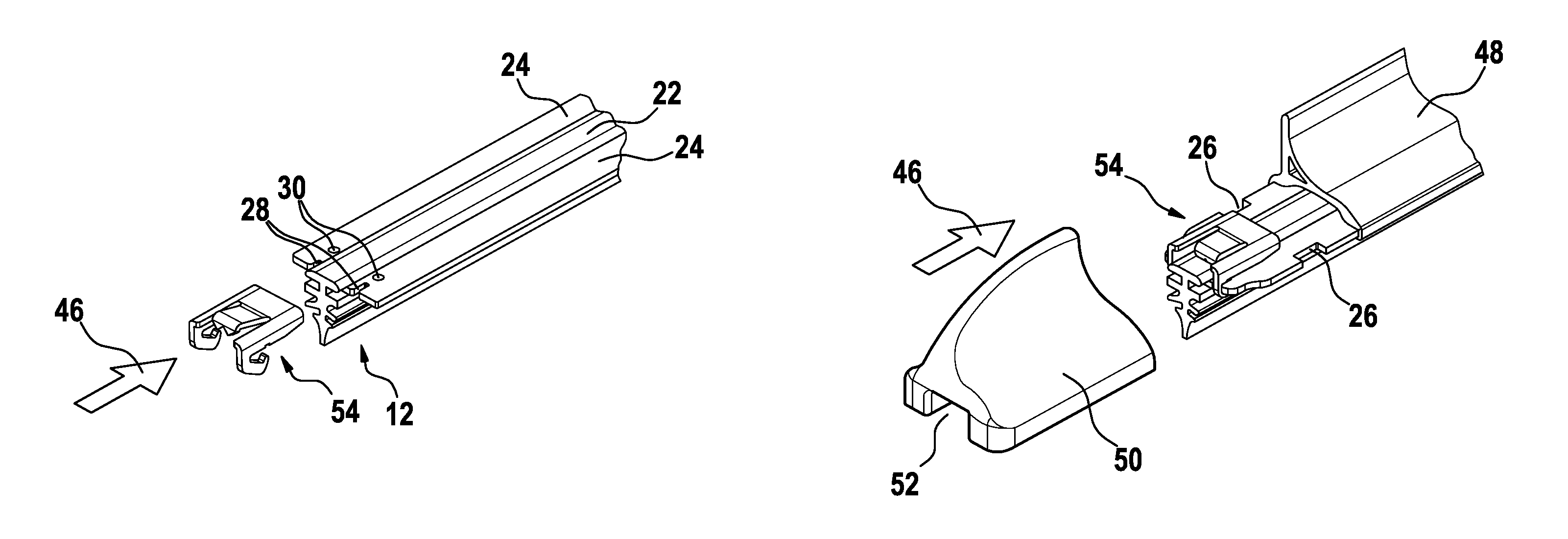
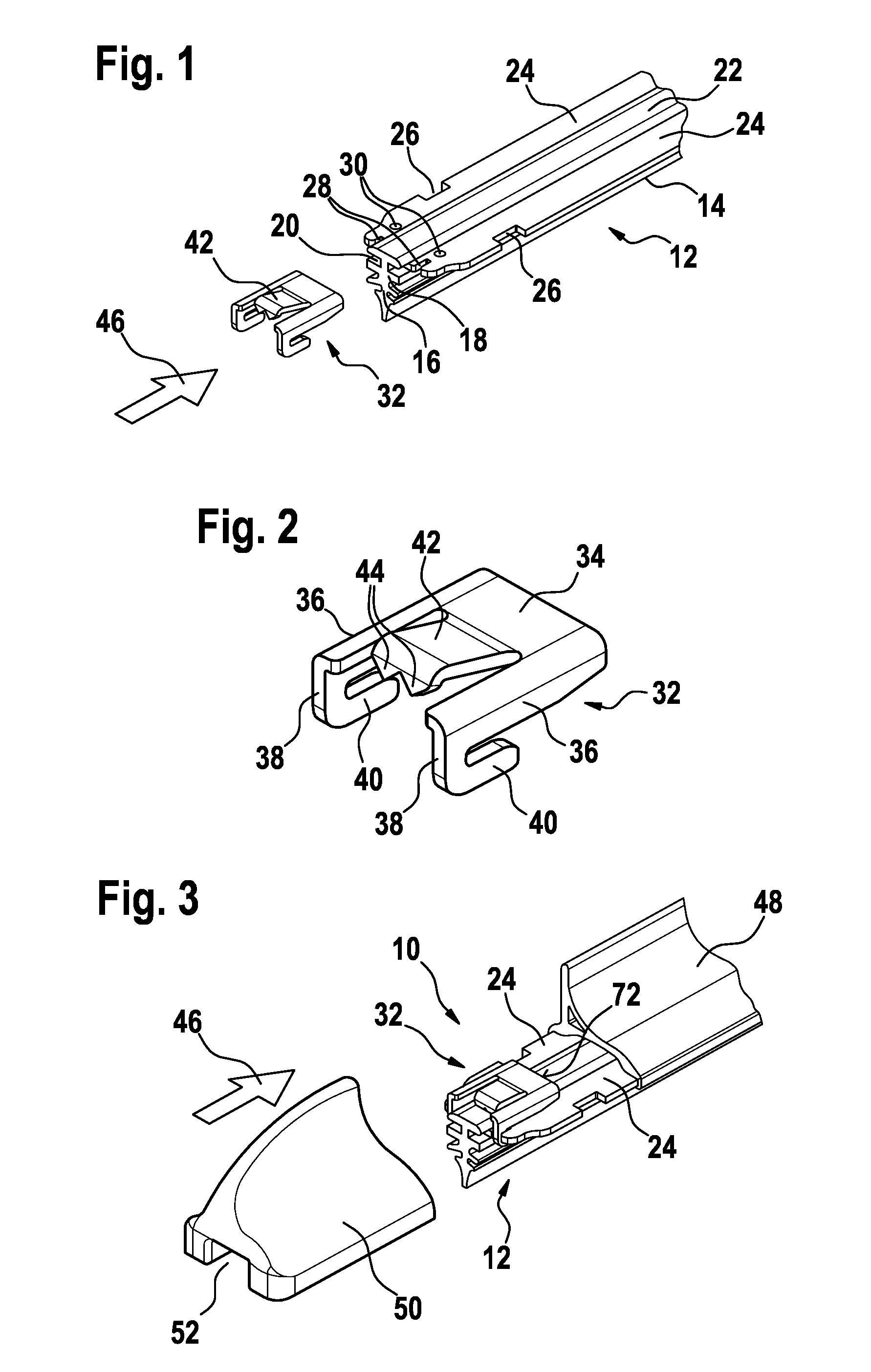
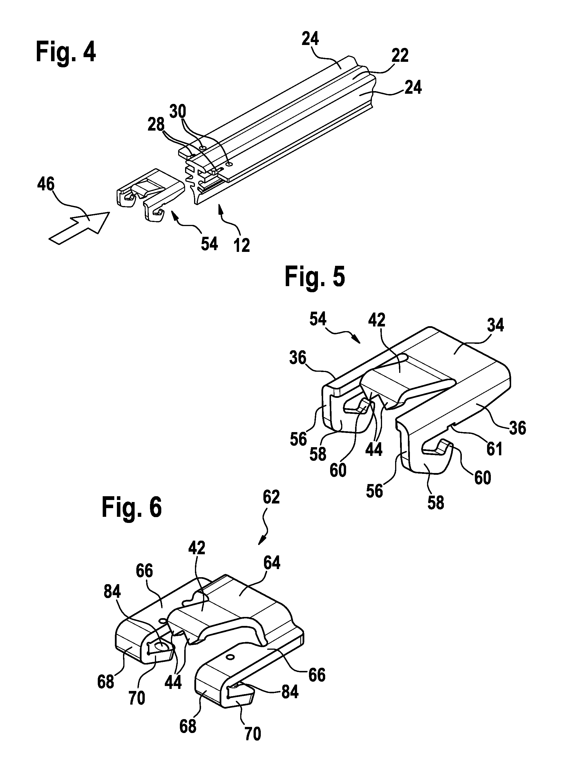
[0023]An essential component of a wiper blade 10 is the wiper strip 12 thereof which slides by means of a wiper lip 14 over a vehicle window (not illustrated) during a wiping movement. The wiper lip 14 is connected via a tilting web 16 to a head strip 18. The latter has longitudinal grooves 20 on both sides, which are upwardly bounded by a back strip 22 of the head strip 18. Spring rails 24 are inserted as a resiliently elastic supporting element into the longitudinal grooves 20 and protrude for a distance from the longitudinal grooves. A spoiler 48 and end caps 50 are guided on said part of the spring rails 24.
[0024]In the exemplary embodiment according to FIGS. 1 to 5, the spring rails 24 are connected to each other by a bridge 32. The latter is produced from a sheet-metal plate by punching and bending, two side parts 36 being angled approximately at right angles from a central part 34. A tab 42 is punched out between the side parts 36. The free end of said tab, on which two claws...
PUM
Abstract
The object of the invention is a wiper blade (10) with a wiper strip (12), in the lateral longitudinal grooves (20) of which spring rails (24) are inserted as springy supporting elements. The ends of the spring rails (24) are connected with one another by a bridge (32, 54, 62, 76) in that side parts (36, 66, 80) of the bridge (32, 54, 62, 76) are supported at the upper side of the spring rail (24) and engage recesses (28, 30) of the spring rails (24), whereas a middle part (34, 64, 78) of the bridge (32, 54, 62, 76) bridges a back strip (22) of the wiper strip (12), which forms the upper boundary of the longitudinal grooves (20). It is proposed that the spring rails (24), at their front faces, have short slots (28), which extend in the longitudinal direction of the spring rails (24) and which are engaged by the I-shaped angle pieces (38, 56) of the bridge (52, 54). Lower legs (40, 58) of the angle pieces (38, 56) are directed towards the middle of the spring rails (24), gripping these from below.
Description
BACKGROUND OF THE INVENTION[0001]The invention relates to a wiper blade.[0002]DE 10 2005 052 258 A1 discloses a wiper blade of the type in question, in which the ends of two spring rails embedded in longitudinal grooves of a wiper strip are connected to each other by a bridge. The bridge has side parts which run parallel to the spring rails and are supported thereon while a central part of the bridge spans a back strip of the wiper strip. Holes are provided in the spring rails, in the region of the ends thereof, through which parts of the side parts reach and, on that side of the spring rails which faces away from the central part, are plastically deformed in such a manner that the bridge is connected fixedly to the spring rails. In this manner, the spring rails are at a constant distance to each other over the length thereof during operation, and therefore the head strip of the wiper strip is not wedged between the spring rails but rather can easily be matched to the curvature of a...
Claims
Application Information
Patent Timeline
Application Date:The date an application was filed.
Publication Date:The date a patent or application was officially published.
First Publication Date:The earliest publication date of a patent with the same application number.
Issue Date:Publication date of the patent grant document.
PCT Entry Date:The Entry date of PCT National Phase.
Estimated Expiry Date:The statutory expiry date of a patent right according to the Patent Law, and it is the longest term of protection that the patent right can achieve without the termination of the patent right due to other reasons(Term extension factor has been taken into account ).
Invalid Date:Actual expiry date is based on effective date or publication date of legal transaction data of invalid patent.

