Bled diffuser fed secondary combustion system for gas turbines

a secondary combustion system and gas turbine technology, applied in the field of gas turbines, can solve the problems of reducing the overall efficiency of the gas turbine, negatively affecting the combustion of the combustors, and airflow entering the combustor section of the gas turbine that exhibits a non-uniform velocity profil

Active Publication Date: 2013-02-26
GE INFRASTRUCTURE TECH INT LLC
View PDF12 Cites 37 Cited by
  • Summary
  • Abstract
  • Description
  • Claims
  • Application Information

AI Technical Summary

Problems solved by technology

Thus, the formation of a boundary layer may result in an airflow entering the combustor section of a gas turbine that exhibits a non-uniform velocity profile.
This can negatively impact combustion within the combustors and reduce the overall efficiency of a gas turbine.
Moreover, significant flow losses may result when the boundary layer separates from the diffuser wall, which can occur when the angle of divergence of the diffuser wall(s) is too wide.
Consequently, however, the improved performance of a bled diffuser is often offset by the reduction in overall efficiency and performance of the gas turbine caused by bleeding pressurized air from the main airflow.
Specifically, bleeding potions of the air exiting the compressor section reduces the amount of compressed air available to cool turbine components or to increase the turbine inlet pressure.

Method used


Image

  • Bled diffuser fed secondary combustion system for gas turbines
  • Bled diffuser fed secondary combustion system for gas turbines
  • Bled diffuser fed secondary combustion system for gas turbines

Examples


Embodiment Construction

[0017]Reference now will be made in detail to embodiments of the present subject matter, one or more examples of which are illustrated in the drawings. Each example is provided by way of explanation and not limitation of the present subject matter. In fact, it will be apparent to those skilled in the art that various modifications and variations can be made in the present subject matter without departing from the scope or spirit of the present subject matter. For instance, features illustrated or described as part of one embodiment, can be used with another embodiment to yield a still further embodiment. Thus, it is intended that the present subject matter covers such modifications and variations as come within the scope of the appended claims and their equivalents.

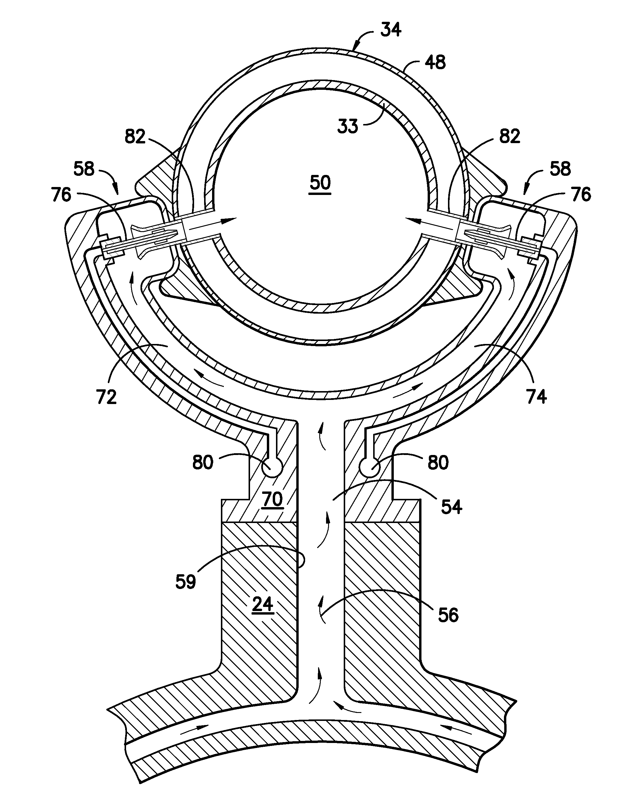
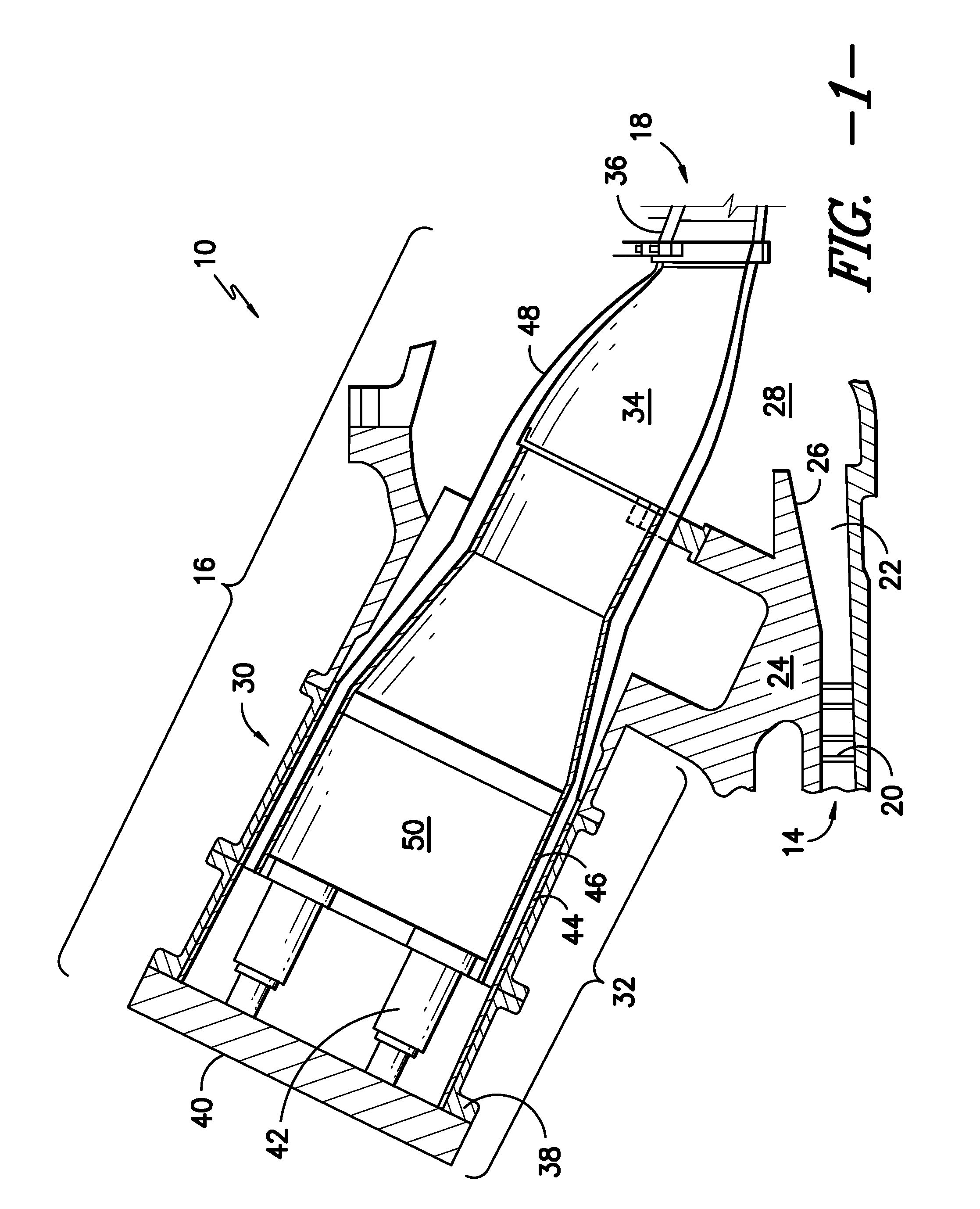
[0018]Referring to FIG. 1, a simplified drawing of a portion of a gas turbine 10 is illustrated. The gas turbine 10 comprises a compressor section 14 configured to pressurize air flowing into the turbine 10. Pressurized a...


PUM


Abstract

The present subject matter provides a system for modifying static pressure recoveries and emissions formation within a gas turbine. The system includes a bled diffuser positioned downstream from a compressor section of the gas turbine and a bleed duct extending from the bled diffuser. The bleed duct may be configured to direct bleed air from the pressurized airflow exiting the compressor section to a secondary combustion system located downstream from the main combustion system in a combustor. The bleed air flowing into the secondary combustion system may be mixed with fuel to form an air / fuel mixture.

Description

FIELD OF THE INVENTION[0001]The present subject matter relates generally to gas turbines and particularly to improving the efficiency of a gas turbine. More particularly, the present subject matter relates to a system and method for feeding bleed air from a bled diffuser to a secondary combustion system in a combustor to improve the overall efficiency of a gas turbine.BACKGROUND OF THE INVENTION[0002]In order to improve the efficiency of the combustion of fuel and air within a combustor, gas turbines typically include a diffuser designed to reduce the velocity and increase the static pressure of the pressurized airflow exiting the compressor section of the gas turbine. A diffuser may generally comprise at least one diverging diffuser wall, which allows the pressurized airflow to spread or diffuse over the length of the diffuser. However, as the pressurized airflow flows through the diffuser, friction along the diffuser wall(s) creates a boundary layer, wherein the velocity of the ai...

Claims


Application Information

Patent Timeline
Patent Type & Authority Patents(United States)
IPC IPC(8): F02C9/00F02C1/00
CPCF01D9/06F23R3/346F02C7/222
Inventor BERRY, JONATHAN DWIGHTHUGHES, MICHAEL JOHN
Owner GE INFRASTRUCTURE TECH INT LLC
Why Eureka
Try Eureka