System box for accommodating aircraft systems

a system box and aircraft system technology, applied in the field of aircraft system integration, can solve the problems of corresponding time and work expenditure, difficulty in further integration of aircraft systems, electrics or air conditioning, etc., and achieve the effects of saving space in the crown area, reducing the weight of the primary structure, and optimizing the seating of the cr

Inactive Publication Date: 2013-02-26
AIRBUS OPERATIONS GMBH
View PDF17 Cites 6 Cited by
  • Summary
  • Abstract
  • Description
  • Claims
  • Application Information

AI Technical Summary

Benefits of technology

[0021]It may be an important advantage of the invention that stiffening of the CRC can be optimised, i.e. designed so as to be of a more lightweight nature, because a large component of load transmission is handled by the system box.
[0022]Since the system box as a secondary structure provides load relief to the primary structure, in this area further weight advantages in the primary structure can be achieved. Likewise, further space in the crown area may be saved. Thus, weight saving in the entire aircraft may be achieved. Moreover, time savings in the production and installation process of the cabin and of the entire aircraft are important advantages of the invention.
[0023]In this arrangement, in further future developments, the system box can comprise still further regions.
[0024]According to a further exemplary embodiment of the present invention the second region is designed for the structural connection of a crew rest compartment to the system box.
[0025]Since the system box, also known as an integrated system attachment box, box or support, acts as a secondary structure within the aircraft, connection of a crew rest compartment entirely by means of the second region of the system box is possible. This can mean that the entire weight and all the tension loads, compression loads and inertia loads that arise as a result of the connected monument or the connected crew rest compartment can be absorbed by the second region. Thus, no further attachment means for the crew rest compartment are necessary. As shown, for example, in FIG. 2, this second region can be designed as a horizontal bearing surface onto which the crew rest compartment can be placed, and to which horizontal bearing surface said crew rest compartment can subsequently be attached. In this arrangement a further vertical contact surface between the two objects can arise. This can lead to further stowage space being created.
[0026]According to a further exemplary embodiment of the present invention the system box comprises a single component.

Problems solved by technology

The development, design, construction and installation of these structures is correspondingly complex.
Further integration of aircraft systems, for example electrics or air conditioning, is correspondingly difficult because time and again braces extend transversely to the normal system paths.
This also means that a modular combination of crew rest compartments or of various systems comprising crew rest compartments is associated with considerable expenditure in time and work.
This solution is also not optimal from the point of view of weight.

Method used


Image

  • System box for accommodating aircraft systems
  • System box for accommodating aircraft systems
  • System box for accommodating aircraft systems

Examples


Embodiment Construction

[0062]Below, exemplary embodiments of the present invention are described with reference to the figures.

[0063]In the following description of the figures the same reference characters are used for identical or similar elements.

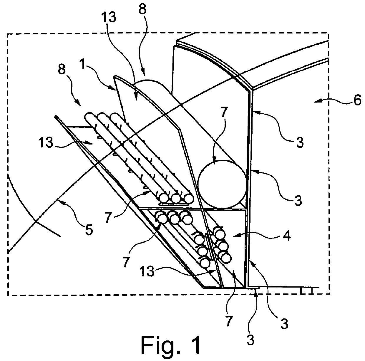
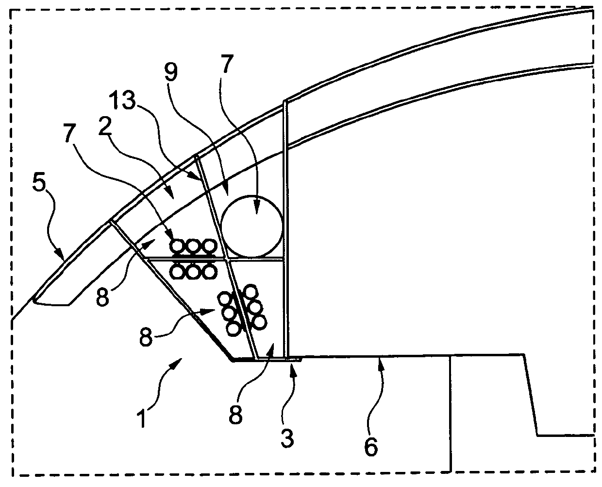
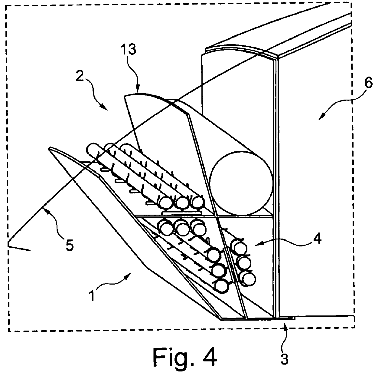
[0064]FIGS. 1 and 4 show a three-dimensional oblique view of an exemplary embodiment of the system box 1 according to the invention. In this arrangement the third region 4 is divided into different segments 8 in which various aircraft systems 7 are accommodated. The individual segments can be separated from each other by means of various segment walls 13. In this arrangement the minimum distance between different lines 7 can be reduced, for example, as a result of the existence of the segment walls. In the present embodiment the second region 3 is designed in a horizontal plane onto which the monument, for example in the present case the crew rest compartment 6, can be placed, or with which plane said monument can at least establish contact. In this arrangemen...


PUM


Abstract

A system box for accommodating aircraft systems, and for load transmission between an aircraft structure and a crew rest compartment. The system box comprises a first, a second and a third region, wherein the three regions differ from each other. The first region is adapted attachment of the system box to the primary structure of the aircraft, wherein the second region is adapted for mechanical contact with a crew rest compartment for the aircrew. The mechanical contact in turn is adapted for load transmission between the aircraft structure and the crew rest compartment. Necessary aircraft systems are accommodated in the third region of the system box.

Description

CROSS-REFERENCE TO RELATED APPLICATIONS[0001]This application claims the benefit of the filing date of U.S. Provisional Patent Application No. 61 / 008,743 filed Dec. 21, 2007, the disclosure of which is hereby incorporated herein by reference.BACKGROUND OF THE INVENTION[0002]The present invention relates to the integration of aircraft systems. In particular, the invention relates to a system box for accommodating aircraft systems, to a modular kit comprising such system boxes, to the use of a system box in an aircraft, and to an aircraft comprising such a system box.[0003]Accommodation compartments for crewmembers of an aircraft (crew), also called crew rest compartments (CRCs), form part of the prescribed facilities of aircraft in the case of long-duration flights. For example, according to international standards one berth for the flight crew (pilots) is required for flights of a duration of between 8 and 14 hours, and two births for flights exceeding 14 hours.[0004]Such rest zones...

Claims


Application Information

Patent Timeline
Patent Type & Authority Patents(United States)
IPC IPC(8): B64C1/10
CPCB64C1/066B64D11/00Y02T50/46Y02T50/40
Inventor BEENTJES, GIJSBERTUSWARNER, HOLGERWESSELINK, CHRISTIAN
Owner AIRBUS OPERATIONS GMBH
Why Eureka
Try Eureka