Fan case for an aircraft engine

a technology for aircraft engines and fan cases, which is applied in the direction of machines/engines, liquid fuel engines, combustion air/fuel air treatment, etc., can solve the problems of low safety in case of damage, low cost, and low weight of fiber-reinforced plastics, so as to ensure safe landing and sufficient stability of aircraft engines

Active Publication Date: 2018-07-31
FACC
View PDF21 Cites 2 Cited by
  • Summary
  • Abstract
  • Description
  • Claims
  • Application Information

AI Technical Summary

Benefits of technology

[0010]In order to achieve the object according to the invention, the reinforcement ply consists of at least 20 plies of a glass fiber-reinforced plastic and deformation layers are disposed on both sides of the reinforcement ply, which deformation layers have a lower strength than the reinforcement ply. The fan case construction according to the invention is distinguished by at least three layers being provided, namely the inner layer, the reinforcement ply and the outer layer, for which special materials are used to achieve the objects according to the invention, namely the protection of the aircraft engine in case of damage, on the one hand, and the retaining of a certain residual strength of the aircraft engine for a safe landing, on the other hand. In the fan case according to the invention, the two objects are achieved by means of two different components so the materials of these components may be adapted perfectly to the respective object. The reinforcement ply made of a glass fiber-reinforced plastic in the middle is mainly used to prevent a disconnected fan blade from passing through the case and to withstand the impact. Corresponding to this, glass fiber-reinforced plastic is used as it exhibits the best properties with respect to an impact of a fan part. By arranging at least 20 plies made of a glass fiber-reinforced plastic, the usually required strengths are obtained. In aircraft engines with particularly high speed and / or for smaller business jets, a higher number of plies, for example 35 plies, may also be required in order to meet the safety requirements. Due to the position of the installation of the reinforcement ply with the surrounding deformation layers within the fan case, said reinforcement ply is also protected from damage, such as by falling rocks, and the weight advantage may be obtained. On the other hand, the residual strength required for a safe landing in case of damage is mainly ensured by the outer layer of the fan case. Preferably, the objective fan case is especially suited for aircraft engines with very high speeds (>10000 revolutions per minute) in which the kinetic energy of a disconnected part of the fan is particularly high. Depending on the design, the weight of the fan case may be reduced between 30% and 50% with respect to steel constructions and by up to 10% with respect to titanium constructions.
[0011]At least one deformation layer may be formed by a honeycomb structure. Such a honeycomb structure is characterized by a particularly low weight. In case of damage, the deformation layer is deformed accordingly, and at least the outer layer of the fan case is prevented from unacceptably high deformation.
[0014]On the inner layer of the fan case, an abrasive layer made of a deformable material may be disposed in the region of the fan. By using such an abrasive layer made of a deformable material, the air gap between the fan of the aircraft engine and the inner layer of the fan case may be further reduced since the fan blade having the largest outer diameter cuts a corresponding shape into the abrasive layer.
[0015]The abrasive layer may be made of a glass fiber-reinforced resin or filled honeycomb cores. Such materials have proven particularly useful and are sufficiently soft with respect to the fan blades, which are usually made of titanium or titanium alloys.
[0016]By disposing a deflection ring made of a material having a higher strength than the deformation layers between the inner layer and the reinforcement ply in the region of the fan, safety may be improved in case of a breaking fan blade and / or material may be saved in the inner layer and / or reinforcement layer while retaining the same degree of safety. The deflection ring is used to deflect the radially occurring forces, which are substantially punctual, to the sides and thus counteract destruction of the fan case and / or engine housing.
[0018]Alternatively, the deflection ring may also be made of an aramid fiber-reinforced plastic, for example Kevlar®. Such fiber-reinforced plastics have a lower weight than metals, but are also correspondingly more expensive.
[0012]At least one deformation layer may also be formed by a foam material. By selecting adequate foam materials and possibly combining it with the deformation layer consisting of a honeycomb structure, the weight and / or deformability may be further improved. Plastics such as acrylonitrile butadiene styrene copolymer (ABS), polymethacrylimid (PMI) and the like are used as the foam material.
[0019]If the deflection ring has a wedge-shaped cross-section with an inclined surface oriented towards the fan, the radially occurring force originating from a disconnected part of a fan blade may be deflected and distributed to the sides so that, consequently, the risk of destruction of the fan case or engine housing and the hazard for the aircraft and the passengers may be reduced.
[0020]The outer layer and the inner layer of the fan case are preferably made of a carbon fiber-reinforced plastic. The outer layer of the fan case, in particular, is formed by an accordingly high number of layers of a carbon fiber-reinforced plastic in order to provide sufficient stability to the aircraft engine in case of damage and ensure a safe landing of the aircraft.

Problems solved by technology

EP 2 096 269 A2 and EP 1 344 895 A2 describe engine linings which are used for optimizing the airflow within the engine, but do not provide safety in case of damage when a fan blade breaks.
Many constructions of fan cases made of a fiber-reinforced plastic are relatively labor-intensive in production and / or require a multiplicity of material plies so the weight advantage with respect to metal fan cases is no longer present or only present to a very limited extent.
Due to the small size of the deflection ring with respect to the entire fan case, the weight disadvantage it causes is negligible.
Such fiber-reinforced plastics have a lower weight than metals, but are also correspondingly more expensive.

Method used


Image

  • Fan case for an aircraft engine
  • Fan case for an aircraft engine

Examples


Embodiment Construction

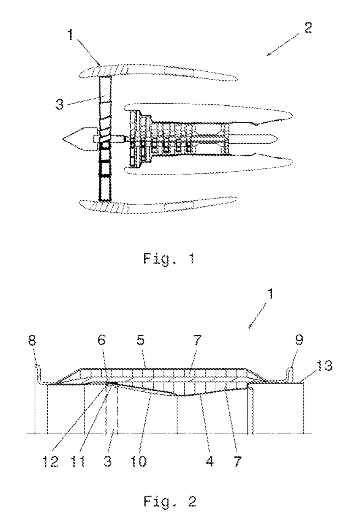
[0024]FIG. 1 illustrates an aircraft engine 2, partially in section, in an arrangement having a fan case 1 disposed in the region of the fan 3. Typically, a fan case 1 consists of a cylindrical jacket having fastening flanges and possible strengthening ribs or the like integrated therein and / or attached thereto. The fan case 1 is connected to the remaining engine housing, which is again arranged on corresponding fastening elements, usually wings.

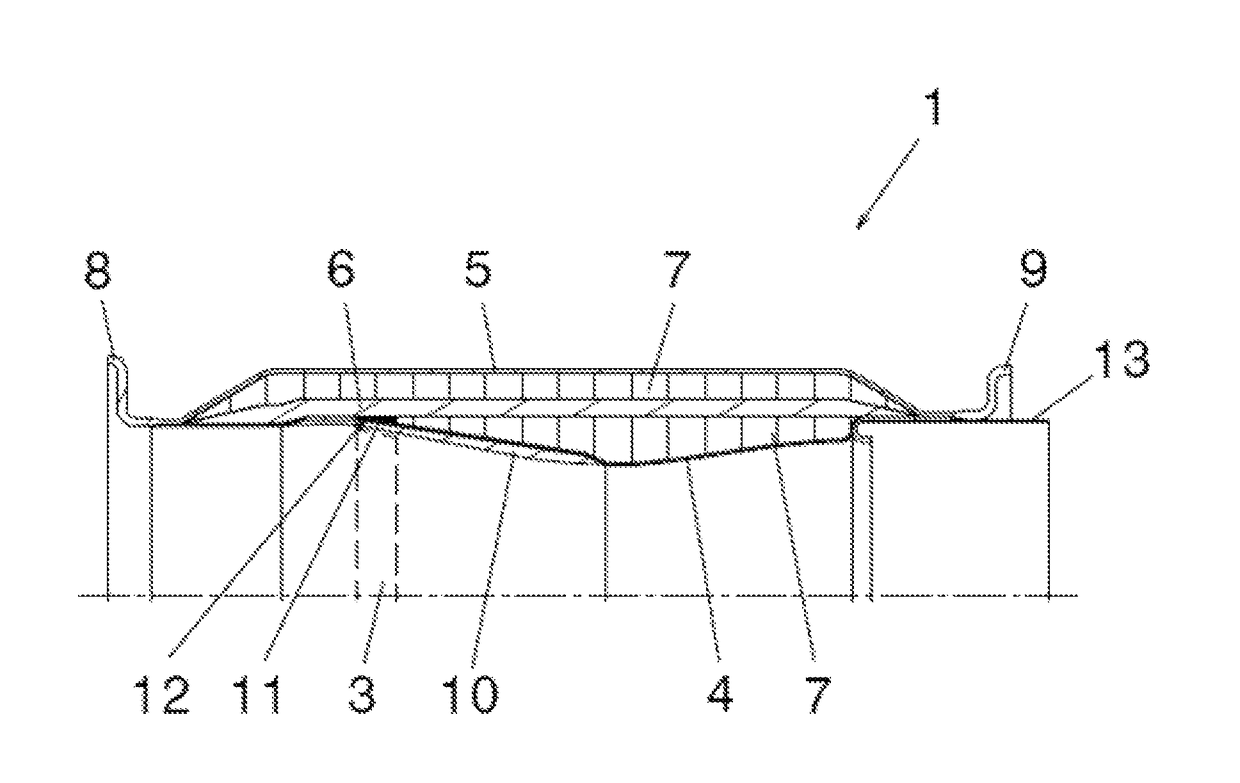
[0025]FIG. 2 shows a part of a fan case 1 designed according to the invention, illustrated in section. The fan case 1 includes an inner layer 4 designed according to the aerodynamic requirements of the aircraft engine 2 and an outer layer 5 as well as a reinforcement ply 6 disposed between the inner layer 4 and the outer layer 5, and deformation layers 7 disposed on both sides of the reinforcement ply 6. Depending on the aircraft engine 2, the reinforcement ply 6 is formed by at least 20 plies of a glass fiber-reinforced plastic and is mainl...


PUM

PropertyMeasurementUnit
strengthaaaaaaaaaa
abrasiveaaaaaaaaaa
ductilityaaaaaaaaaa

Abstract

The invention relates to a fan case for an aircraft engine in the region of the fan thereof, comprising a plurality of substantially cylindrically arranged fiber-reinforced plastic layers that are joined together, wherein a reinforcement ply made of a glass fiber-reinforced plastic is disposed between an inner layer and an outer layer. According to the invention, the reinforcement ply consists of at least 20 plies of a glass fiber-reinforced plastic, and that deformation layers are disposed on both sides of the reinforcement ply, which deformation layers have a lower strength than the reinforcement ply.

Description

CROSS-REFERENCE TO RELATED APPLICATIONS[0001]The present application is a U.S. National Phase of International Patent Application Serial No. PCT / AT2015 / 050251, entitled “FAN CASE FOR AN AIRCRAFT ENGINE,” filed on Oct. 9, 2015. International Patent Application Serial No. PCT / AT2015 / 050251 claims priority to Austrian Patent Application No. A 50723 / 2014, filed on Oct. 10, 2014. The entire contents of each of the above-cited applications are hereby incorporated by reference for all purposes.TECHNICAL FIELD[0002]The invention relates to a fan case and / or blower case for an aircraft engine in the region of the fan thereof, comprising a plurality of substantially cylindrically arranged fiber-reinforced plastic layers that are joined together, wherein a reinforcement ply made of a glass fiber-reinforced plastic is disposed between an inner layer and an outer layer.BACKGROUND AND SUMMARY[0003]Fan cases of aircraft engines are used to prevent destruction of the engine in the region of the fan...

Claims


Application Information

Patent Timeline
Patent Type & Authority Patents(United States)
IPC IPC(8): B32B17/04F02C7/04F04D29/52B32B17/10B32B3/12B32B5/24F01D21/04F01D25/24B32B17/06
CPCB32B17/04B32B3/12B32B5/245B32B17/066B32B17/10073F01D25/24F02C7/04F01D21/045F05D2240/14B32B2250/05B32B2605/18F04D29/526B29C70/446F01D11/125F01D11/127F02K3/04F02K3/06F05D2300/603Y02T50/60F04D29/52
Inventor FUERST, WALTERHAUGENEDER, ERNSTHOREJSI, KONSTANTINSTUBNA, BORISHOELLRIGL, ANDREAS
Owner FACC
Why Eureka
Try Eureka