Axle arrangement

a technology of axles and axles, applied in the direction of resilient suspensions, rigid suspensions, pivoted suspension arms, etc., can solve the problems of increased fuel consumption, increased stress on tires, and not always assuming the desired position of wheels, so as to facilitate manufacturing and reduce stress

Inactive Publication Date: 2013-02-26
BENTELER AUTOMOBILTECHNIK GMBH
View PDF18 Cites 1 Cited by
  • Summary
  • Abstract
  • Description
  • Claims
  • Application Information

AI Technical Summary

Benefits of technology

[0009]According to another advantageous feature of the present invention, the axle member bracket may also be constructed in the form of a fork-shaped metal sheet. Constructing the wheel carrier bracket and / or axle member bracket in the form of a fork-shaped metal sheet reduces weight and thereby decreases fuel consumption as well as provides benefits on the side of the unsprung wheel with respect to agility and comfort. The presence of a pivotable support of the wheel carrier bracket enables to adjust the toe of a vehicle axle. As the wheel carrier bracket pivots, the wheel carrier that is securely fixed thereto swings at the same time and thereby is able to change the toe direction of the vehicle wheel. This is beneficial because the toe can be adjusted during initial installation of the axle arrangement and can be readjusted during repair work. As a result of the attained optimum toe adjustment of all wheels, tire wear and fuel consumption is minimized and safe travel conditions of the chassis are ensured.
[0024]An axle arrangement according to the present invention has a further benefit of being applicable, even when the axles are driven. Joints or also cardan joints already arranged in the drive shafts provide the required compensation in order to reduce stress encountered during toe adjustment through relative pivoting of wheel carrier to axle member. Thus, the present invention is also applicable for driven axles. The two fasteners, namely the stud bolt and the eccentric bolt in the event the other coupler is configured as eccentric bolt, may be arranged spaced apart at a distance sufficient to allow disposition of the drive shaft in midsection between these two fasteners.

Problems solved by technology

When installing the rigid axle in the motor vehicle or during operation of the motor vehicle, the wheels do not always assume the desired position.
Manufacturer's based tolerances lead to situations in which the rigid axles are not positioned at an orthogonal angle relative to the vehicle longitudinal axis and thus are skewed in relation to the typically adjustable axles with independent wheel suspension, mostly front axles.
The tires which are also positioned at a slant are exposed to greater wear.
Incorrect wheel position, especially incorrect toe, also increases fuel consumption.
In addition, incorrectly aligned wheels can only transmit slight lateral guide forces and compromise safety in an extreme case.
In particular the rear axle demands greater safety considerations because in the event the rear of the vehicle swerves and causes oversteering, uncontrollable driving conditions may arise.

Method used


Image

  • Axle arrangement
  • Axle arrangement
  • Axle arrangement

Examples


Embodiment Construction

[0029]Throughout all the figures, same or corresponding elements may generally be indicated by same reference numerals. These depicted embodiments are to be understood as illustrative of the invention and not as limiting in any way. It should also be understood that the figures are not necessarily to scale and that the embodiments are sometimes illustrated by graphic symbols, phantom lines, diagrammatic representations and fragmentary views. In certain instances, details which are not necessary for an understanding of the present invention or which render other details difficult to perceive may have been omitted.

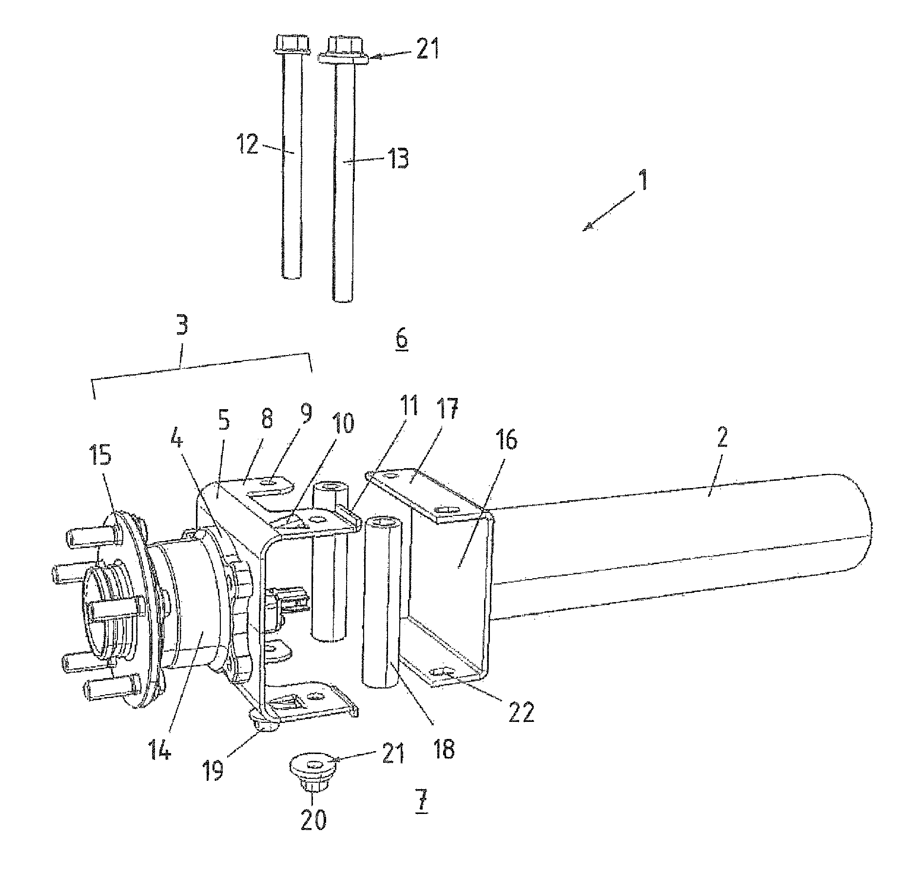
[0030]Turning now to the drawing, and in particular to FIG. 1, there is shown an exploded view of one embodiment of an axle arrangement according to the present invention, generally designated by reference numeral 1. The axle arrangement 1 includes an axle member 2 and a wheel suspension 3. The wheel suspension 3 includes a wheel carrier 4 and a wheel carrier bracket 5 coupl...


PUM


Abstract

An axle arrangement includes an axle member and an axle member bracket arranged on the axle member. A wheel suspension having a wheel carrier bracket is constructed in the form of a fork-shaped metal sheet and swingably supported on the axle member bracket for wheel alignment, with a wheel carrier being arranged on the wheel carrier bracket.

Description

CROSS-REFERENCES TO RELATED APPLICATIONS[0001]This application claims the priority of German Patent Application, Serial No. 10 2010 020 816.7, filed May 18, 2010, pursuant to 35 U.S.C. 119(a)-(d), the content of which is incorporated herein by reference in its entirety as if fully set forth herein.BACKGROUND OF THE INVENTION[0002]The present invention relates to an axle arrangement for a motor vehicle.[0003]The following discussion of related art is provided to assist the reader in understanding the advantages of the invention, and is not to be construed as an admission that this related art is prior art to this invention.[0004]Conventional wheel suspensions for motor vehicles include, i.a., attachment points to the vehicle body, bearings, at least one guide rod, suspension system, and wheel carrier secured to the guide rod. The guide rod can be designed as transverse control arm or semi-trailing arm. When a rigid axle is involved, springs in the form of leaf springs are oftentimes ...

Claims


Application Information

Patent Timeline
Patent Type & Authority Patents(United States)
IPC IPC(8): B62D17/00
CPCB62D17/00B60B35/006
Inventor HENKSMEIER, THOMASHOCHAPFEL, ERIK
Owner BENTELER AUTOMOBILTECHNIK GMBH
Why Eureka
Try Eureka