Direct-connect fuse unit for battery terminal

a fuse unit and battery terminal technology, applied in the direction of electrical discharge lamps, emergency protective devices, coupling device connections, etc., can solve the problems of inability to arrange the fuse unit in a limited space around the battery terminal, the output side terminal section cannot be stably placed, and the footprint of the fuse unit is likely to increase, so as to enhance the assembly work, avoid breakage, and stabilize the position

Active Publication Date: 2013-02-26
SUMITOMO WIRING SYST LTD
View PDF11 Cites 7 Cited by
  • Summary
  • Abstract
  • Description
  • Claims
  • Application Information

AI Technical Summary

Benefits of technology

[0008]In view of the above problems, an object of the present invention is to provide a direct-connect fuse unit for a battery terminal that can be prevented from increasing in size and can mount various kinds of electrical components.
[0011]In addition, since the electrical component housing is separated from the casing, it is possible to provide the electrical component housing in the fuse unit while avoiding to upsize the direct-connect fuse unit for the battery terminal.
[0013]According to the direct-connect fuse unit for the battery terminal in the second aspect of the present invention, it is possible to strongly fit the electrical component housing in the casing by utilizing the space at the corner of the direct-connect fuse unit for the battery terminal. Since the engaging reaction exerted in the one orthogonal side wall can be supported on the other orthogonal side wall, it is possible to stably maintain a mounting condition of the electrical component housing.
[0015]According to the direct-connect fuse unit for the battery terminal in the third aspect of the present invention, when the electrical component housing is mounted on the casing, the engaging projection is guided and pushed into the engaging cut-out portion, and the electrical component housing is positioned in the casing. Accordingly, it is possible to stably position the electrical component housing in the casing at the initial stage of mounting the electrical component housing on the housing mounting recess, thereby avoiding breakage of the engaging projection on account of misalignment of the engaging projection at the initial stage and enhancing an assembling work.
[0016]In addition, since the housing mounting recess is provided on its side wall with the engaging cut-out portion, it is possible to downsize the positioning mechanism including the electrical component housing and the housing mounting recess while restraining the projecting length of the engaging projection of the electrical component housing from increasing downward.
[0017]According to the present invention, since the connecting terminal is bent in the plate thickness direction of the conducting hardware and the electrical component housing that contains the connecting terminal is separated from the casing, it is possible to provide the electrical component housing on the direct-connect fuse unit for a battery terminal while avoiding to upsize the fuse unit.

Problems solved by technology

However, because the conducting hardware spreads in a flat plate-like manner in the conventional direct-connect fuse unit for the battery terminal, a footprint of the fuse unit around the battery terminal is likely to increase.
Consequently, the fuse unit cannot be arranged in a limited space around the battery terminal.
Furthermore, because the casing is molded integrally with the conducting hardware, the output side terminal section is limited to a simple structure in which a stud bolt is provided on an exposed conducting hardware.
Also, there is a problem that the electrical components that can be attached to the direct-connect fuse unit for the battery terminal will be subject to constraints.

Method used


Image

  • Direct-connect fuse unit for battery terminal
  • Direct-connect fuse unit for battery terminal
  • Direct-connect fuse unit for battery terminal

Examples


Embodiment Construction

[0035]Referring now to the drawings, embodiments of a direct-connect fuse unit for a battery terminal will be described below.

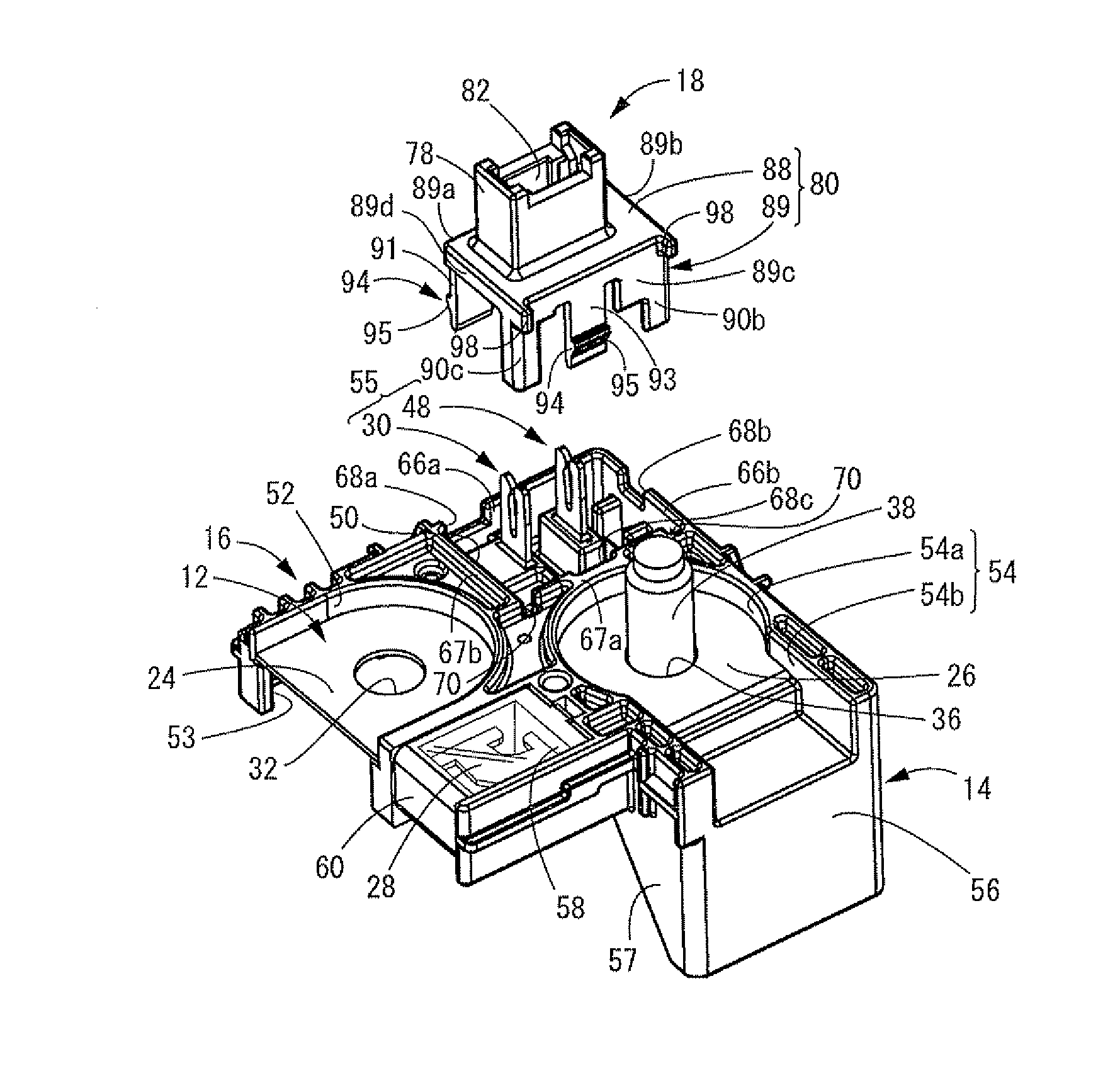
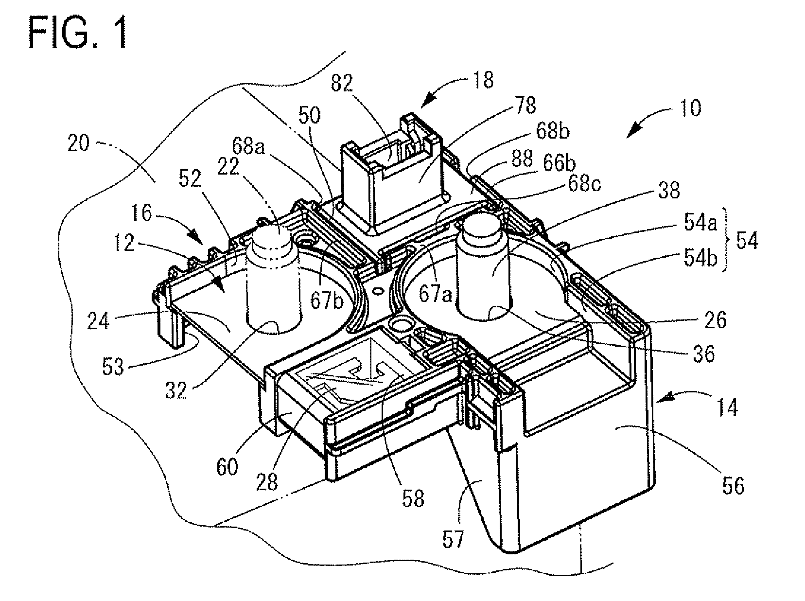
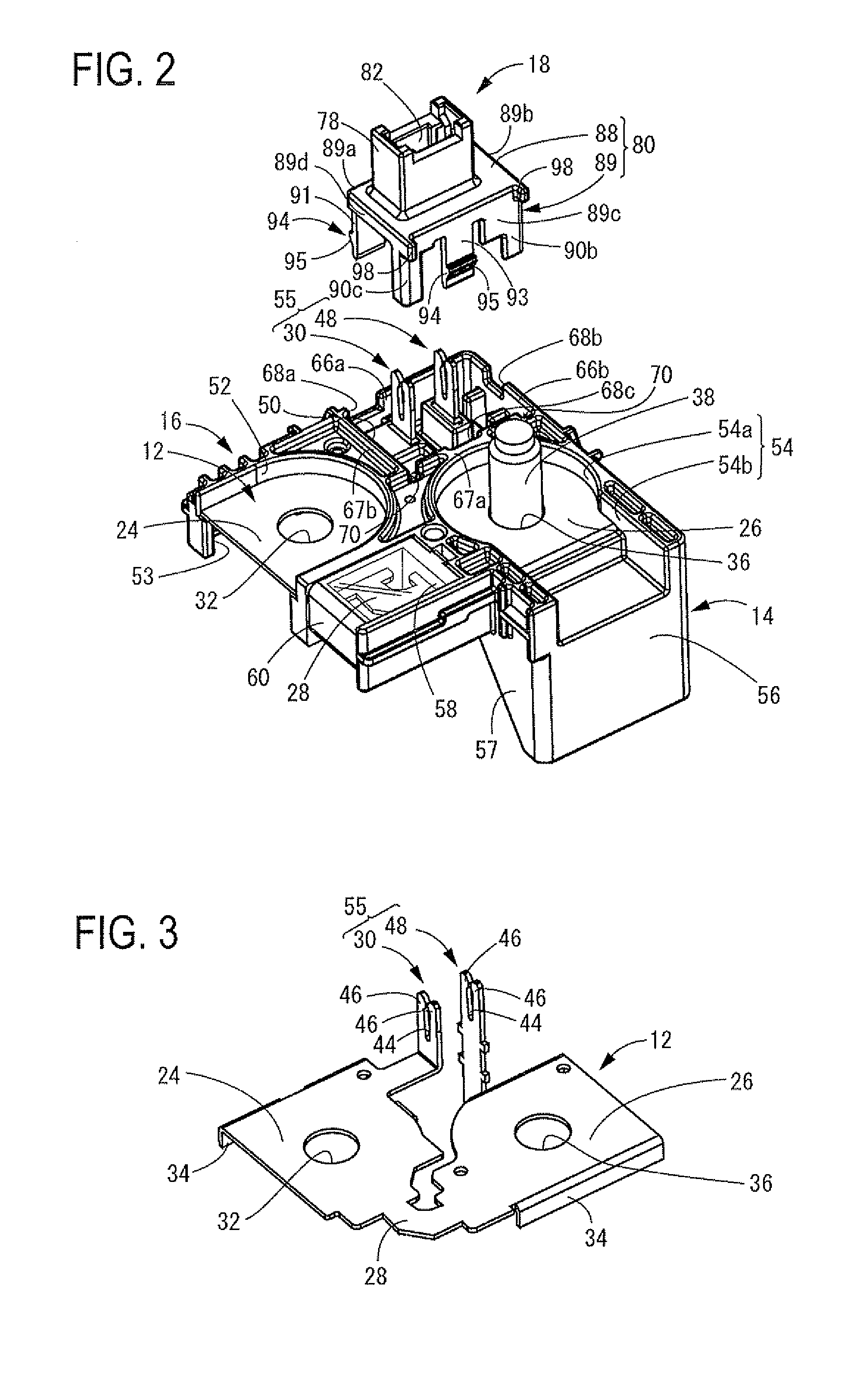
[0036]FIG. 1 shows a perspective view of a first embodiment of a direct-connect fuse unit 10 for a battery terminal. FIG. 2 shows an exploded perspective view of the direct-connect fuse unit 10 for the battery terminal in order to explain an assembled state. The fuse unit 10 may include a conducting hardware 12 and a casing 14 for covering front and rear sides of the fuse unit 10. A fuse housing (an electrical component housing) 18 that may be formed into a discrete member may be fitted and mounted on a top surface of a unit main body 16 comprising the conducting hardware 12 and casing 14. The use unit 10 constructed above may be mounted on a battery 20 for a motor vehicle shown by imaginary lines 20 in FIG. 1 to be connected to a battery terminal 22. Hereinafter, for convenience of explanations, upper and lower directions in FIGS. 1 and 2 designate upper and...


PUM


Abstract

An object of the present invention is to provide a direct-connect fuse unit for a battery terminal that can restrain from being upsized and can mount various kinds of electrical components. A conducting hardware is integrally provided with a connecting terminal. The connecting terminal is bent in a plate thickness direction of the conductive hardware to project from a surface of a casing. An electrical component housing contains and holds an external electrical component connected to the connecting terminal. The electrical component housing is separated from the casing and is adapted to be fitted in the casing.

Description

BACKGROUND[0001]1. Technical Field[0002]The exemplary embodiments to a direct-connect fuse unit for a battery terminal and more particularly relates to a fuse unit that is directly connected to a terminal of a battery mounted on a motor vehicle.[0003]2. Background Art[0004]An electrical power terminal of a battery for a motor vehicle (hereinafter, referred to a battery terminal) is connected through a direct-connect fuse unit for the battery terminal to an output side electrical cable. An electrical power from the battery is supplied through an electrical junction box (a relay box, a fuse box, a junction box, or the like) connected to the output side electrical cable to various kinds of loads. If an excessive current flows in the electrical junction box, a fusing section of the fuse unit is fused to cut off the excessive current to the output side electrical cable, thereby protecting the various kinds of loads connected to the output side electrical cable at a downstream side. Such ...

Claims


Application Information

Patent Timeline
Patent Type & Authority Patents(United States)
IPC IPC(8): H01R13/68
CPCH01R11/287H01R13/696H01R13/688H01R13/506H01H2085/025
Inventor SHIRAKI, TAKASHI
Owner SUMITOMO WIRING SYST LTD
Why Eureka
Try Eureka