
Negative pressure dust collection structure for power tools

a technology of power tools and dust collection structures, which is applied in the direction of grinding machines, metal-working machine components, manufacturing tools, etc., can solve the problems of high dust production at work, common drawbacks, and hazardous to the health of workers, and achieve the effect of improving the dust collection range and efficiency, reducing the efficiency of conventional dust collection structures, and improving the dust collection structur

Active Publication Date: 2013-02-26
XPOLE PRECISION TOOLS
View PDF21 Cites 3 Cited by
  • Summary
  • Abstract
  • Description
  • Claims
  • Application Information

AI Technical Summary

Benefits of technology

The solution achieves more efficient dust collection with uniform suction and reduced energy consumption by accelerating airflow and expanding the dust collection range, effectively addressing the inefficiencies of existing systems.

Problems solved by technology

Some of the power tools aim for drilling, sanding or grinding, and a great amount of dust is produced in the working places during operation.
It is hazardous to the health of workers.
While the aforesaid references provide dust inhalation function, they have a common drawback.
Moreover, the junction of the edge of the opening and the hood forms an angle over seventy degrees, and results in a great power loss of the air at the angle.
In short, the aforesaid problems make suction airflow strength uneven in the hood, and result in a portion of the dust cannot be drawn into the air discharge duct and scatter outside the hood.
Not only the power of the inhalation device connected to the air discharge duct is wasted, it also creates a lot of energy waste.

Method used


Image

  • Negative pressure dust collection structure for power tools
  • Negative pressure dust collection structure for power tools
  • Negative pressure dust collection structure for power tools

Examples


Embodiment Construction

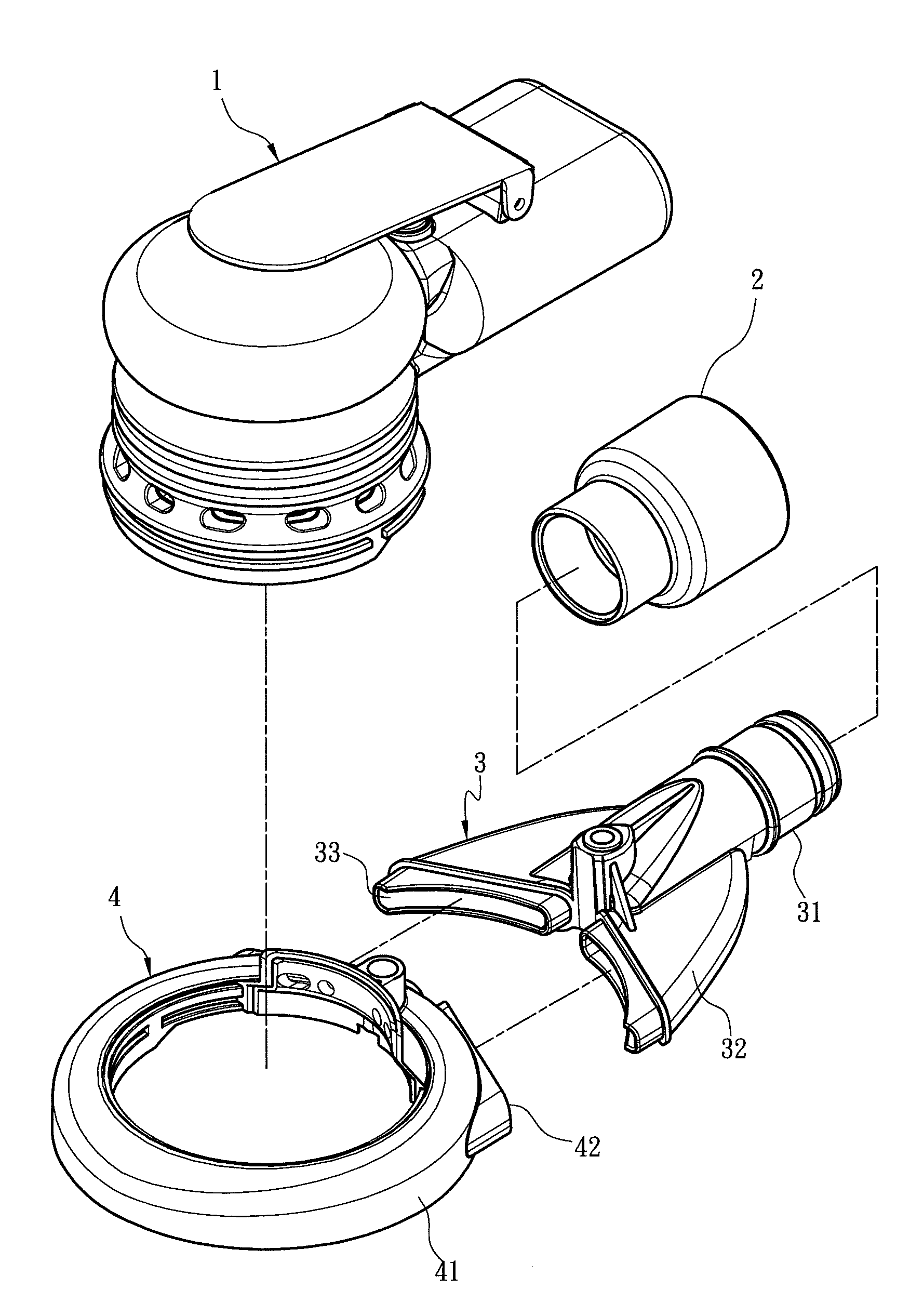
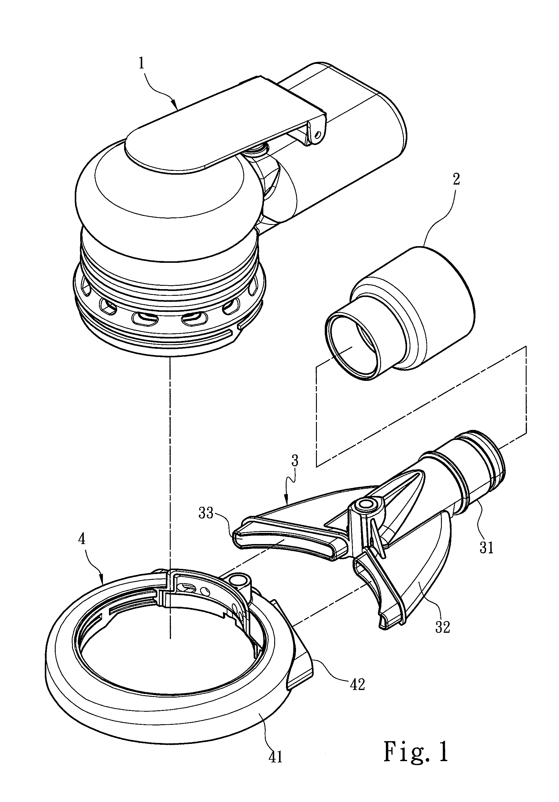
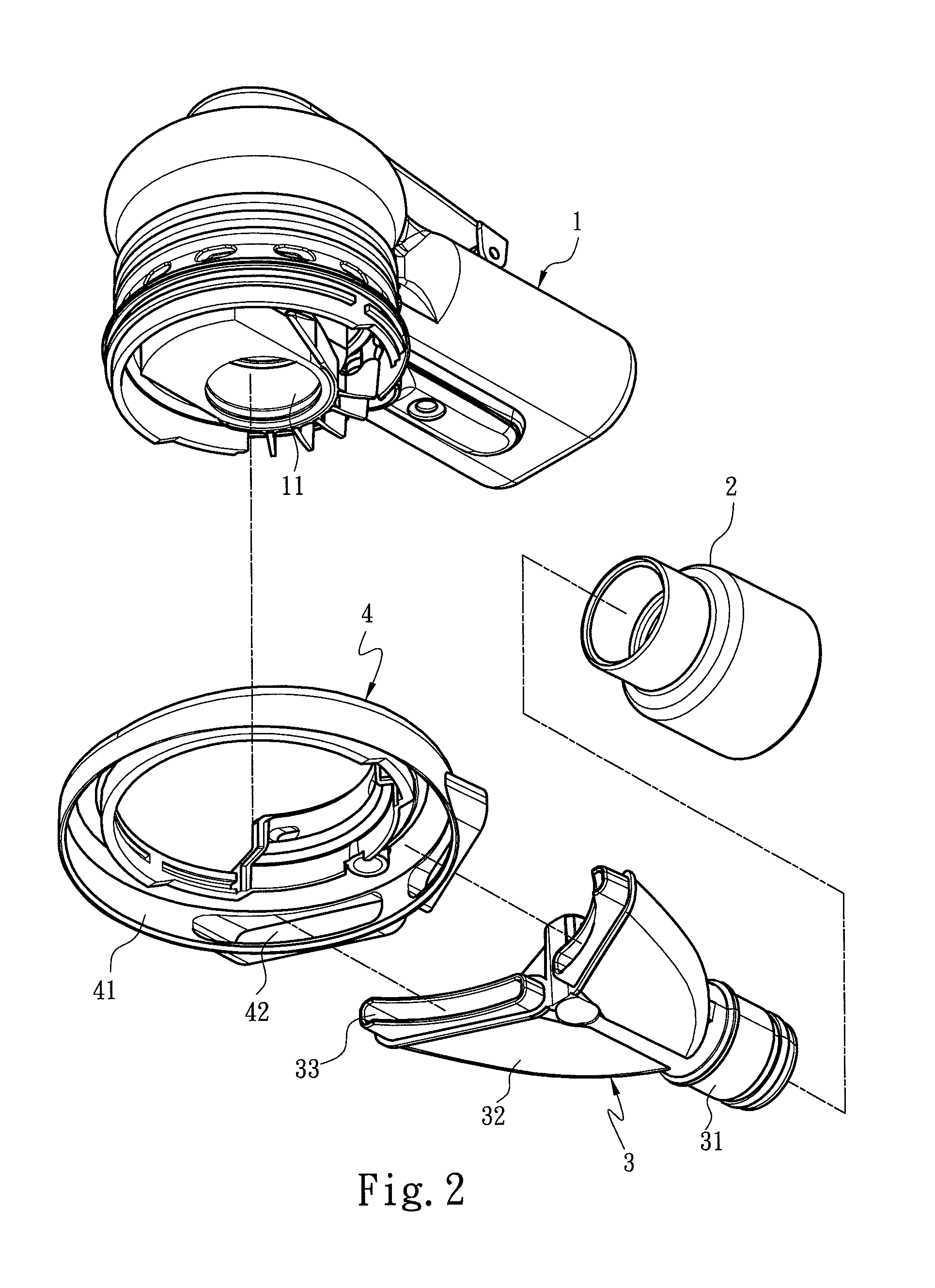
[0012]Please refer to FIGS. 1 through 4, the negative pressure dust collection structure according to the invention is located on a power tool 1 which has an output portion 11 at one end to couple with an application tool operable in a working space surrounded by a dust collection hood 4. The power tool 1 may be a pneumatic or electric mechanism held by a user to control operation of the output portion 11. This is a technique known in the art and forms no part of the invention, thus the internal detailed structure of the power tool 1 is omitted. The dust collection hood 4 is connected to the power tool 1, and has a wall 41 surrounding the working space. The wall 41 has at least one flow conduction vent 42 connected to a negative pressure enhancing duct 3 communicating with an airflow duct 2. The airflow duct 2 is connected to a negative pressure source. Theoretically, airflow stops when air pressure is in a balanced condition, but flows to where the pressure is lower in the event th...


PUM


Abstract

A negative pressure dust collection structure aims to be used on a power tool which is coupled with an application tool operable in a working space surrounded by a dust collection hood. The dust collection hood includes at least one flow conduction vent communicating with an airflow duct through a negative pressure enhancing duct. The negative pressure enhancing duct has a negative pressure enhancing chamber communicating with the flow conduction vent. The negative pressure enhancing chamber is formed at a cross section shrunk gradually from the flow conduction vent towards the airflow duct to increase suction of the negative pressure enhancing duct to collect dust in the dust collection hood. Moreover, the negative pressure enhancing chamber has an opening edge mating the shape of the inner side of the wall of the dust collection hood to increase covering range of the airflow.

Description

FIELD OF THE INVENTION[0001]The present invention relates to a negative pressure dust collection structure for power tools and particularly to a dust collection structure with an improved flow conduction duct.BACKGROUND OF THE INVENTION[0002]Small power tools (including pneumatic or electric ones) are well accepted on the market due to their smaller size and lower prices and energy consumption. The power tools include a wide variety of types, such as emery wheel machines, drilling machines, pneumatic (or electric) wrenches and the like. Some of the power tools aim for drilling, sanding or grinding, and a great amount of dust is produced in the working places during operation. It is hazardous to the health of workers. Hence a lot of improved structures are developed for power tools to solve the dust scattering problem. For instance, R.O.C. patent No. M349818 entitled “Improved grinding machine” provides a casing and a handgrip at one side. The handgrip has an input portion (121) and ...

Claims


Application Information

Patent Timeline
Patent Type & Authority Patents(United States)
IPC IPC(8): B24B55/06
CPCB23Q11/0046B24B55/102
Inventor CHEN, BACH PANGHO
Owner XPOLE PRECISION TOOLS
Learn More