
Camera system and method for amalgamating images to create an omni-focused image

a technology of omni-focused images and camera systems, applied in the field of electronic imaging technology, can solve the problems of large restrictions in technology, inability to produce congruent image production, inconsistent or blurry images,

Inactive Publication Date: 2013-02-26
IIZUKA KEIGO
View PDF13 Cites 10 Cited by
  • Summary
  • Abstract
  • Description
  • Claims
  • Application Information

AI Technical Summary

Benefits of technology

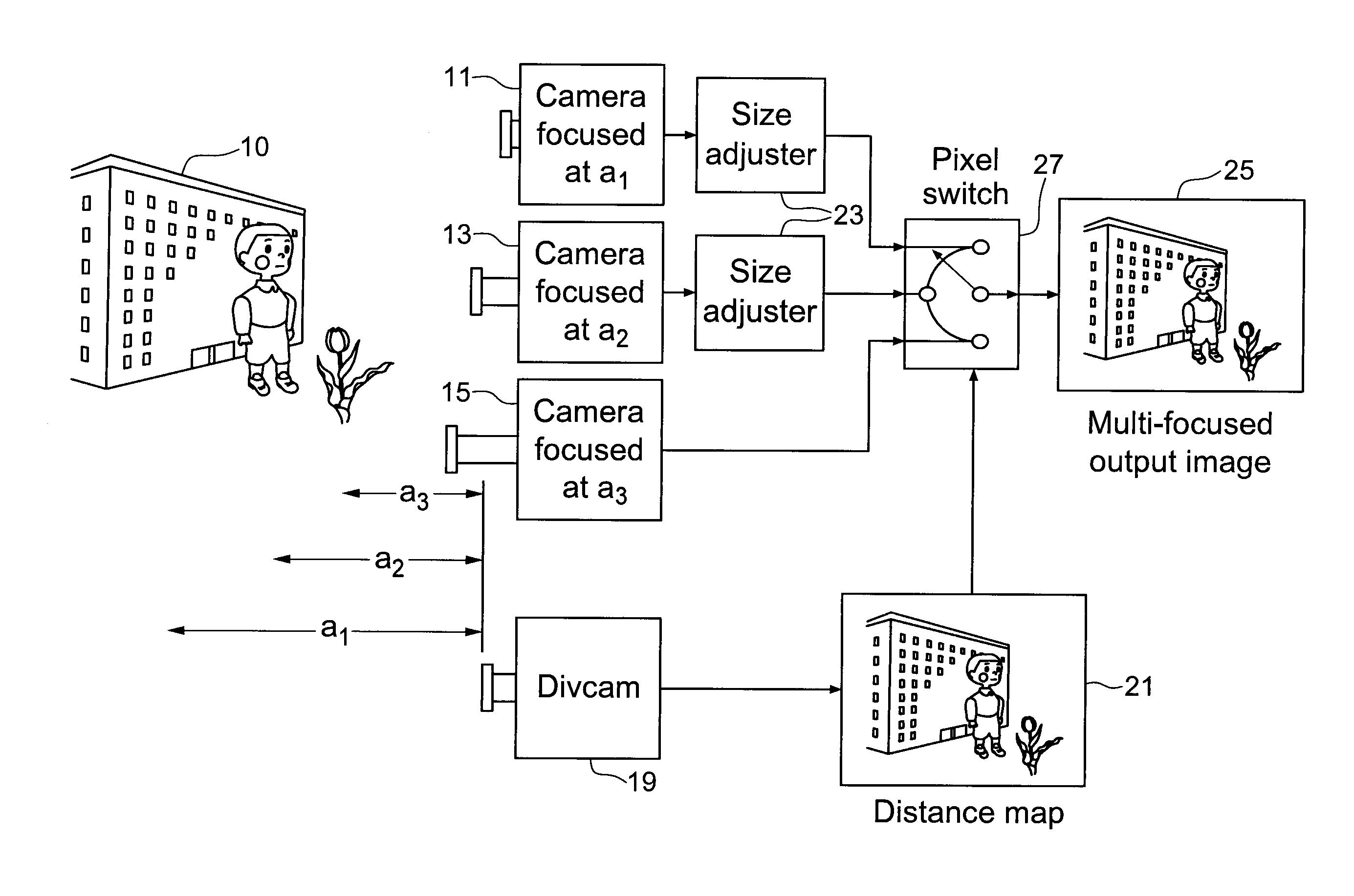
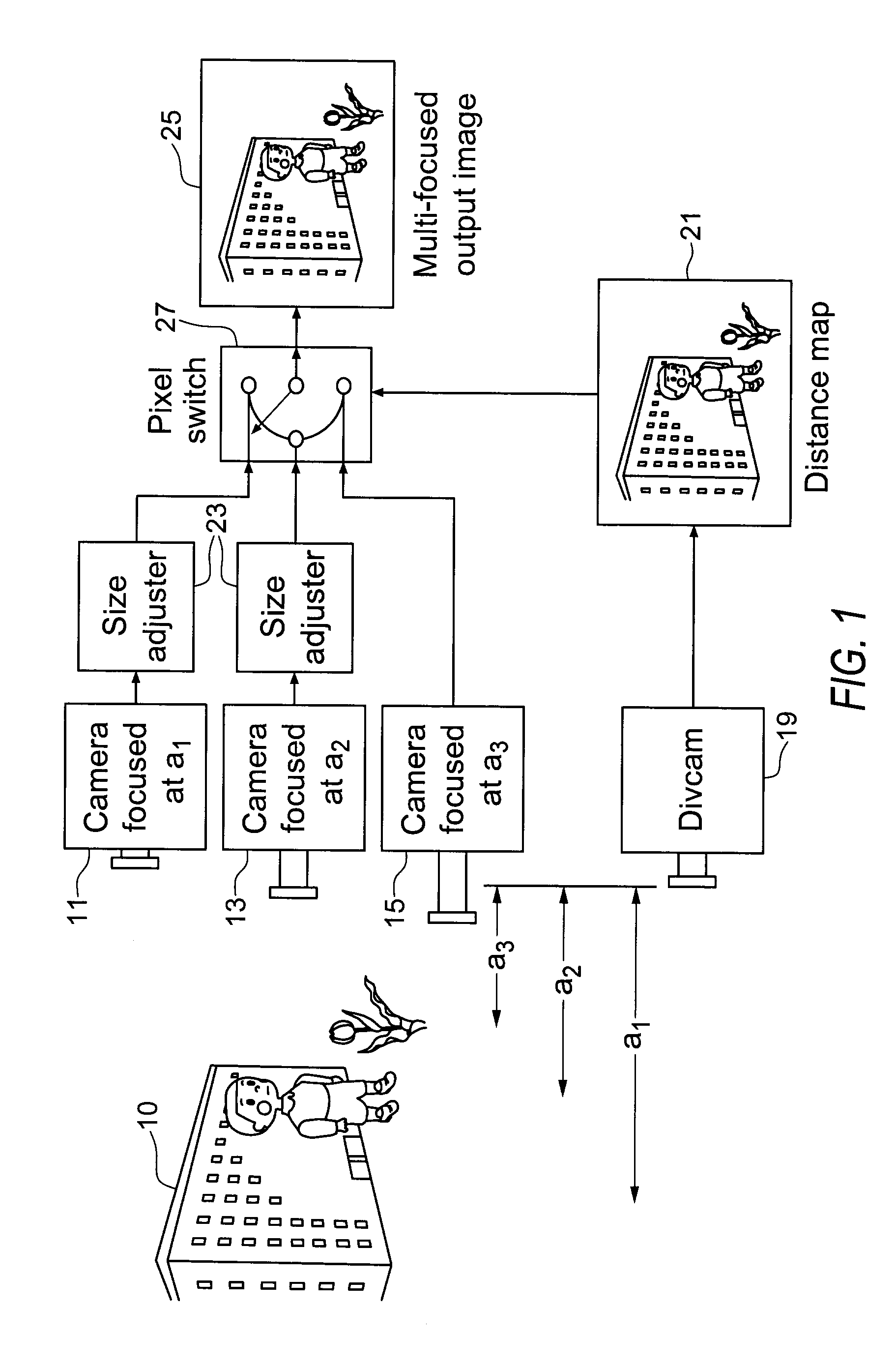
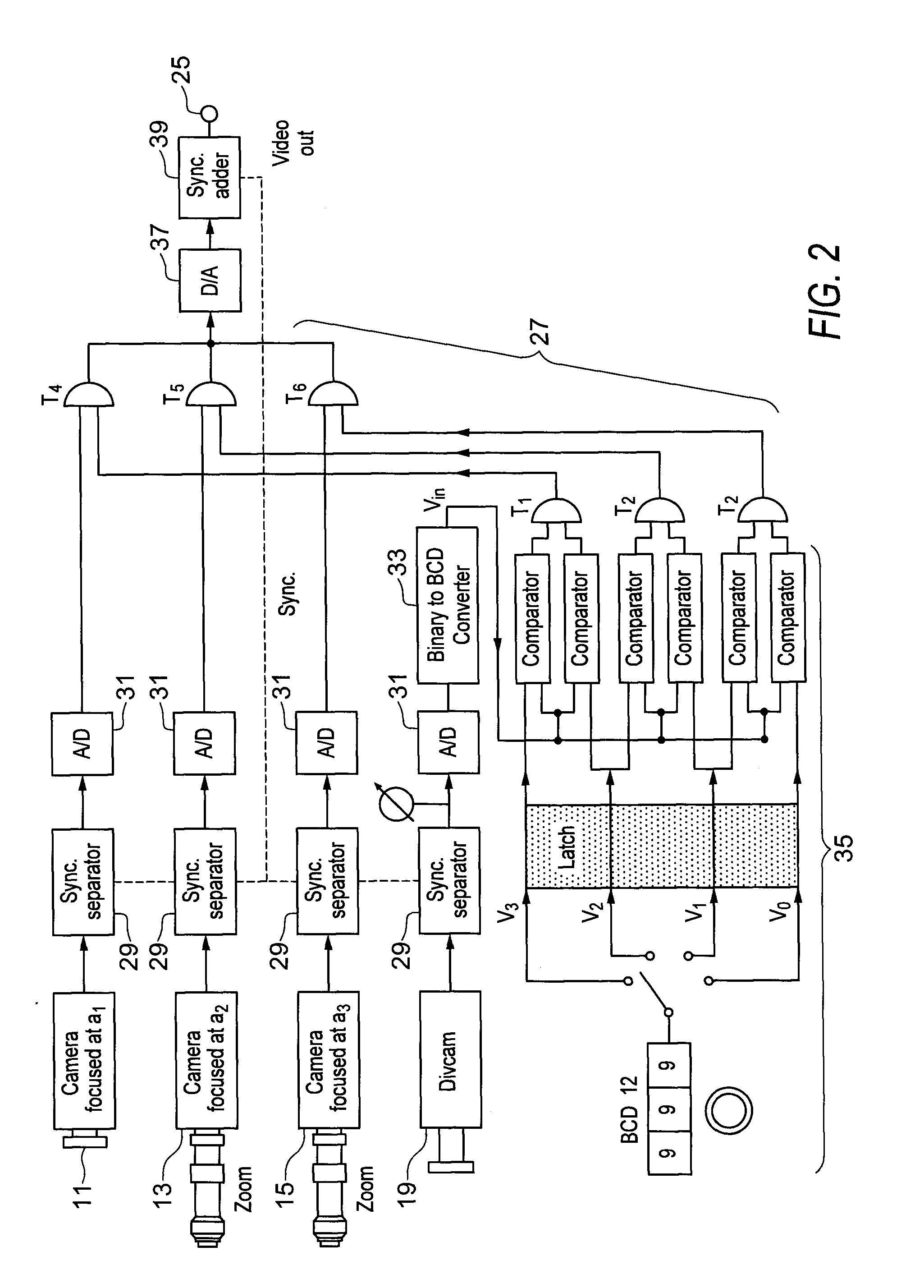
The present patent describes an image system that uses multiple video cameras aimed at a scene, each focused at different distances. The system includes a distance mapping camera that provides information about the objects in the scene. This information is used by a pixel selection tool to select individual pixels from the video outputs, which are then combined to create a single video display. The system can effectively focus and amalgamate the video outputs to create a single image with multiple focal points. The technical effect of this invention is to allow for more complete and precise analysis of a scene with multiple cameras focused at different distances, resulting in a more complete and accurate video output.

Problems solved by technology

However, this technology has been greatly restricted because of its limited ability of producing an image which is focused to only one point in the target scene.
The prior art describe technologies wherein images that are produced tend to lack depth resulting in segments of the image being in focus while other segments are out of focus, producing an inconsistent or blurry image.
The system described in this article allows for the measure of depth of an object and allows for computing synthetic photographs from different view points; however, the system does not allow for congruent image production wherein objects at different distances are all in focus within one image.
Further, the resolution of the image taken by such a camera is limited by the diameter of the microlenses used.

Method used


Image

  • Camera system and method for amalgamating images to create an omni-focused image
  • Camera system and method for amalgamating images to create an omni-focused image
  • Camera system and method for amalgamating images to create an omni-focused image

Examples


Embodiment Construction

[0013]The proposed omni-focused or multi-focused camera (collectively referred to as “omni-focused camera”) mitigates the depth of focus limitations of traditional single-focused cameras. An omni-focused camera refers to a camera that may be operable to generate an image focused on one or more points of objects in the image.

[0014]The omni-focused camera of the present invention electronically combines at least two images of the same scene focused at different distances, taken by means of at least two cameras (one or more video cameras and one distance mapping camera device). In the single video camera implementation of the present invention, the single camera is operable with a scanned focus utility further possessing a memory bank to store the multiple captured images.

[0015]In another implementation of the present invention, three or more cameras may be used (one distance mapping camera and multiple video cameras), in which case the present invention may be operable to amalgamate s...


PUM


Abstract

This invention relates to a system and method for creating an omni-focused image. Specifically, this invention relates to a system and method for electronically amalgamating images using real-time distance information to create an omni-focused image. The system of the invention comprises one or more video cameras aimed at a scene each generating a video output focused at a different distance, a distance mapping camera providing distance information for one or more objects in the scene, and a pixel selection utility wherein the pixel selection utility uses the distance information to select pixels from the video outputs to be used to generate a video display. The system is then operable to focus and amalgamate the video outputs to produce one image with multiple focal points or an omni-focused image.

Description

FIELD OF THE INVENTION[0001]This invention relates to electronic imaging technology. Specifically, this invention relates to a system and method for electronically amalgamating images using real-time distance information to create an omni-focused image.BACKGROUND OF THE INVENTION[0002]The field of electronic imaging technology has been used extensively to capture images in a two dimensional form. However, this technology has been greatly restricted because of its limited ability of producing an image which is focused to only one point in the target scene. The prior art describe technologies wherein images that are produced tend to lack depth resulting in segments of the image being in focus while other segments are out of focus, producing an inconsistent or blurry image. Innovations in this field have focused on image resolution and omni-directional image capturing methods in order to produce congruent images.[0003]One such innovation in this field is described in the article Light ...

Claims


Application Information

Patent Timeline
Patent Type & Authority Patents(United States)
IPC IPC(8): H04N5/262H04N5/232G03B13/00
CPCG06T5/50H04N13/25H04N23/743H04N23/90
Inventor IIZUKA, KEIGO
Owner IIZUKA KEIGO
Learn More