
Method and arrangement for repeater/relay control

a repeater/relay control and control method technology, applied in the field of improved relaying methods in telecommunication systems, can solve the problems of unavoidable delay, df relays, and use that cannot provide full benefit, and achieve the effect of improving relaying and reducing control signaling

Inactive Publication Date: 2013-02-26
TELEFON AB LM ERICSSON (PUBL)
View PDF4 Cites 6 Cited by
  • Summary
  • Abstract
  • Description
  • Claims
  • Application Information

AI Technical Summary

Benefits of technology

The invention improves how information is sent and reduces the need for control signals.

Problems solved by technology

However, since the decoding operation will result in an unavoidable delay the forwarding must take place at a later time instance, i.e. on another radio resource.
Despite the benefits of utilizing AF repeaters, there are a few disadvantages that prevent the use from providing the full benefit of them.
One drawback with repeaters compared to DF relays is that they forward not only signals but also noise and interference.
Furthermore, a major challenge for on-frequency repeaters is to sufficiently suppress the self-interference they induce.
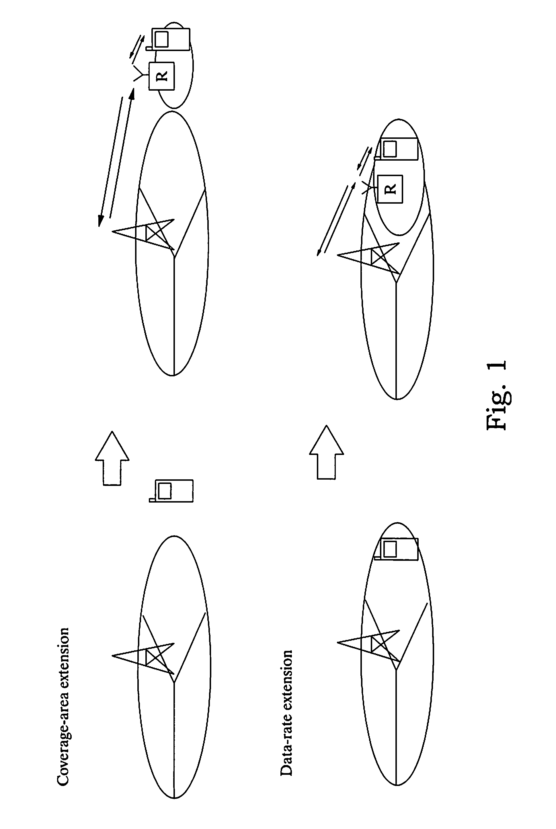
In the coverage extension scenario, the options when it comes to advanced repeater behavior are more limited.
It is not possible to e.g. turn the repeater off even when the repeater does not serve any UEs since that would leave the area with no coverage.
Furthermore, an idle UE would not detect any paging messages sent from the network.
In the coverage area extension case it is also not possible to perform frequency selective repetition on the downlink since that would hinder the UE from receiving the physical downlink control channel (PDCCH) that covers the whole downlink bandwidth.

Method used


Image

  • Method and arrangement for repeater/relay control
  • Method and arrangement for repeater/relay control
  • Method and arrangement for repeater/relay control

Examples


Embodiment Construction

[0039]The present invention will be described in the context of a LTE system; however, it is equally applicable to similar systems utilizing repeaters or repeater nodes.

[0040]To further illustrate the disadvantages of using AF repeaters, some additional problems will be described below. In addition, some specifics relating to control signaling in LTE will be described with relation to the problems solved by the present invention.

[0041]Solutions based on conventional repeaters, as they are described in the background have several shortcomings that need to be overcome to enable a more efficient use of repeaters in telecommunication systems, especially for LTE Advanced systems.

[0042]These disadvantages include:

[0043]Interference problems: For a given user some repeaters may contribute with more interference than signal. Typically, it is desirable to avoid moving the low SNR from the cell edge into the cell center when there is no active cell edge user.

[0044]Repeater cross-couplings may...


PUM


Abstract

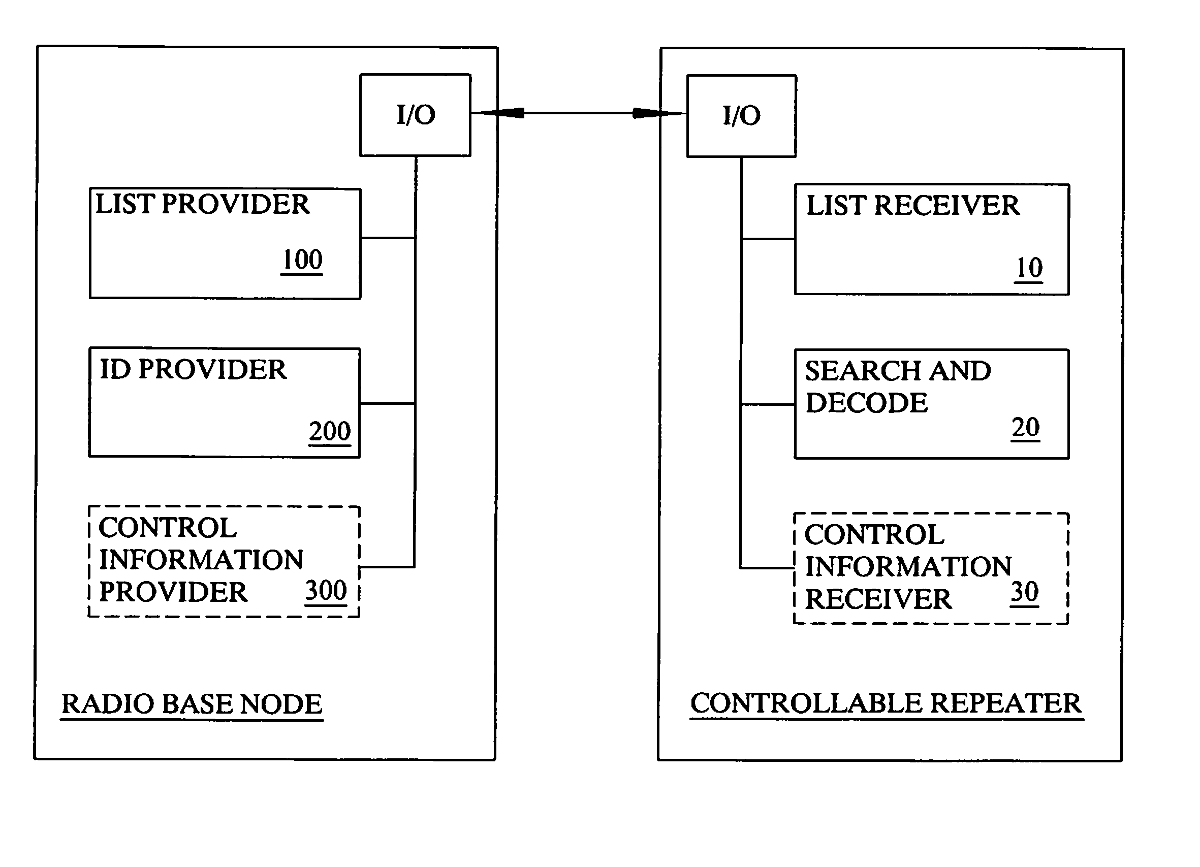
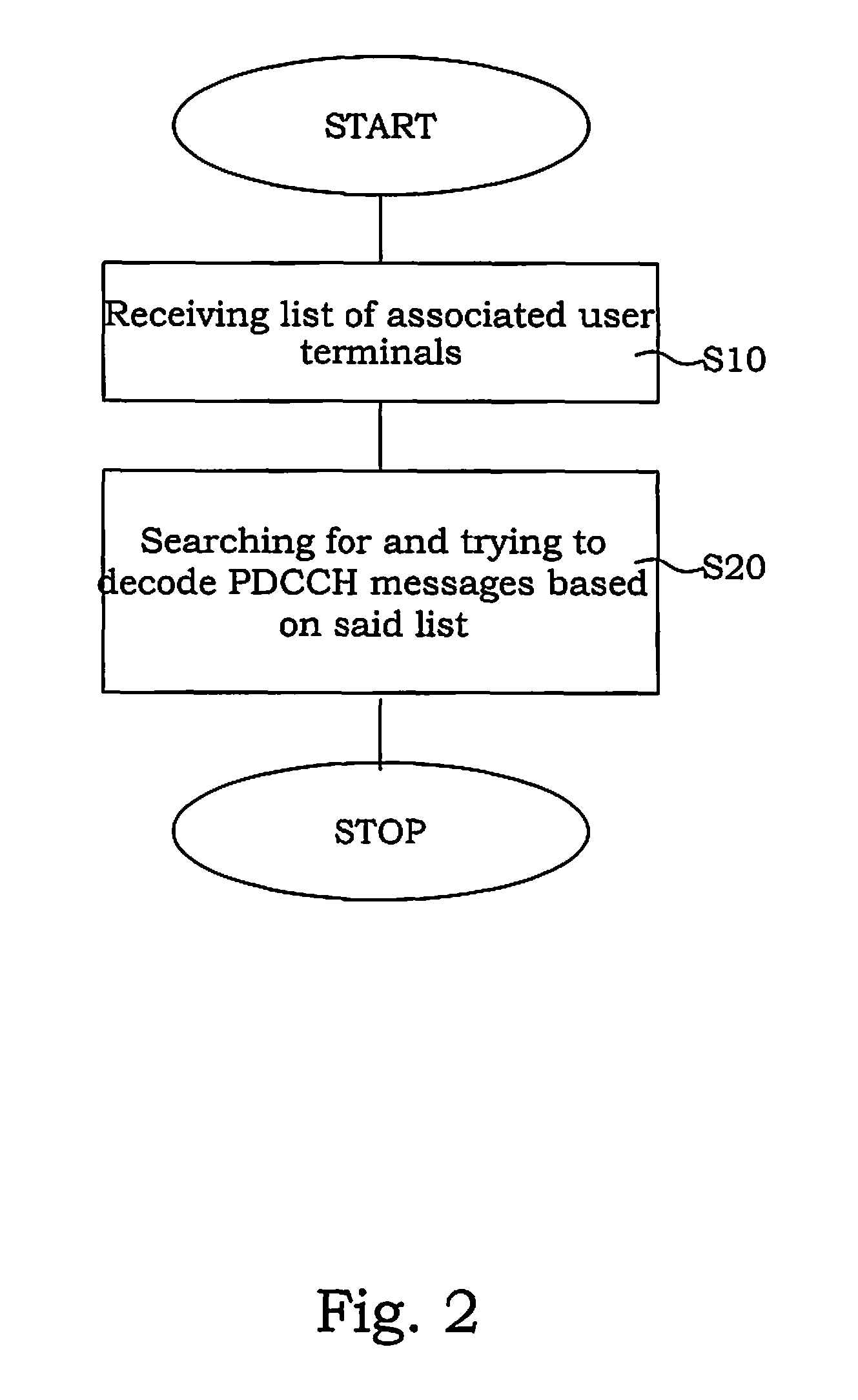
In a method in a controllable repeater in a telecommunication system, said system comprising a radio base station, at least said controllable repeater and a plurality of user terminals, receiving a list of associated user terminal identities for said repeater, and searching for and decoding downlink channel control messages based on said provided list.

Description

CROSS-REFERENCE TO RELATED APPLICATIONS[0001]This application claims the benefit of U.S. Provisional Application No. 61 / 226,068, filed Jul. 16, 2009 and International Application No. PCT / SE2009 / 051015, filed on Sep. 11, 2009, the disclosures which are incorporated herein by reference.BACKGROUND[0002]Abbreviations used herein shall have the following meanings:AF Amplify-and-ForwardCRC Cyclic Redundancy CheckDCI Downlink Control InformationDF Decode-and-ForwardDFTS Decode and Forward TSDL DownlinkFSR Frequency Selective Relay (Repeater)FTR Frequency Translating Relay (Repeater)OFDM Orthogonal Frequency Division MultiplexOFR On-Frequency Relay (Repeater)PDCCH Physical Downlink Control CHannelCRNTI Cell Radio Network Temporary IdentifierTTI Transmission Time IntervalUL Uplink[0003]One recent development within modern telecommunication standards is the so-called Long Term Evolution (LTE) radio interface, and a further development of the LTE, namely LTE Advanced. These are both OFDM based...

Claims


Application Information

Patent Timeline
Patent Type & Authority Patents(United States)
IPC IPC(8): H04W4/00
CPCH04B7/2606H04W8/26H04W72/0406H04W72/20
Inventor BALDEMAIR, ROBERTFRENGER, PAL
Owner TELEFON AB LM ERICSSON (PUBL)
Learn More