Flashlight control circuit

a control circuit and flash technology, applied in the field of flash control circuits, can solve the problems of reducing the maximum energy which may be released at the main flash stage, requiring an additional discharge signal, and still has some technical problems that need to be improved, so as to reduce the error in the luminance of the flash, improve the accuracy, and reduce the transmission delay

Inactive Publication Date: 2005-10-20
IMPRESS ENTERPRISE
View PDF5 Cites 8 Cited by
  • Summary
  • Abstract
  • Description
  • Claims
  • Application Information

AI Technical Summary

Benefits of technology

[0025] According to the principles and objects of the invention, the flash control circuit has the advantages of better precision and lower transmission delay.
[0026] According to the principles and objects of the invention, the flash control circuit has the advantage of reduced error in luminance of the flash after multiple luminance tests.

Problems solved by technology

However, since the flash is generated by discharge of a large capacitor charged with a high voltage, such as 160 uF / 330V, the preflash stage may reduce the maximum energy which may be released at the main flash stage.
Although the technology in this patent may improve the disadvantages in the prior art, it still has some technical problems that need to be improved.
For example, the flash requires an additional discharge signal, and lacks the function of forcing flash generation.
In addition, the control circuit is composed of bi-polar junction transistors, which leads to a slower response speed, a larger transmission delay and has an inclination to over-exposure and imprecise flash control.
Furthermore, too much error may occur in current technology.
Therefore, the technology using preflash to determine the required exposure is not precise enough.
However, this is not the case for currently used cameras with more pixels, in which the flash control has a considerable effect on the resulting image quality.

Method used


Image

  • Flashlight control circuit
  • Flashlight control circuit
  • Flashlight control circuit

Examples


first embodiment

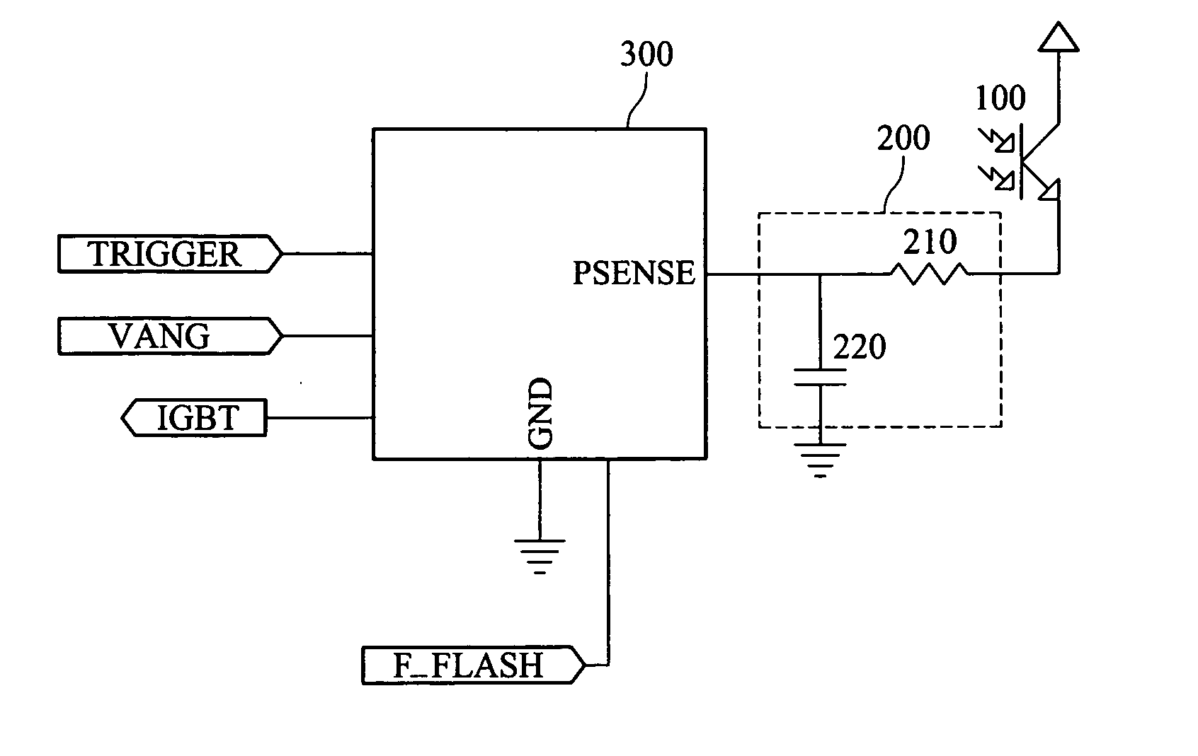
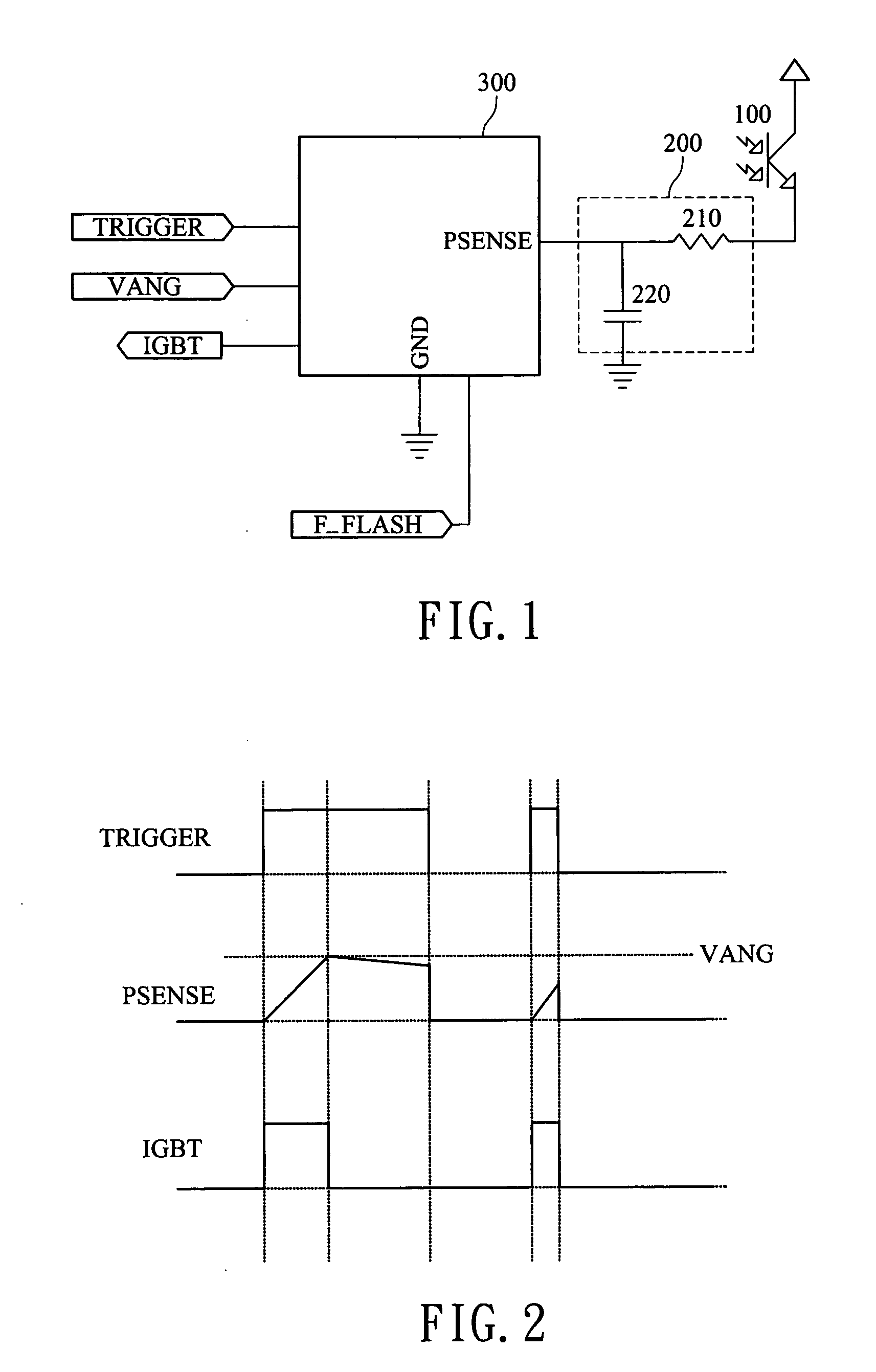
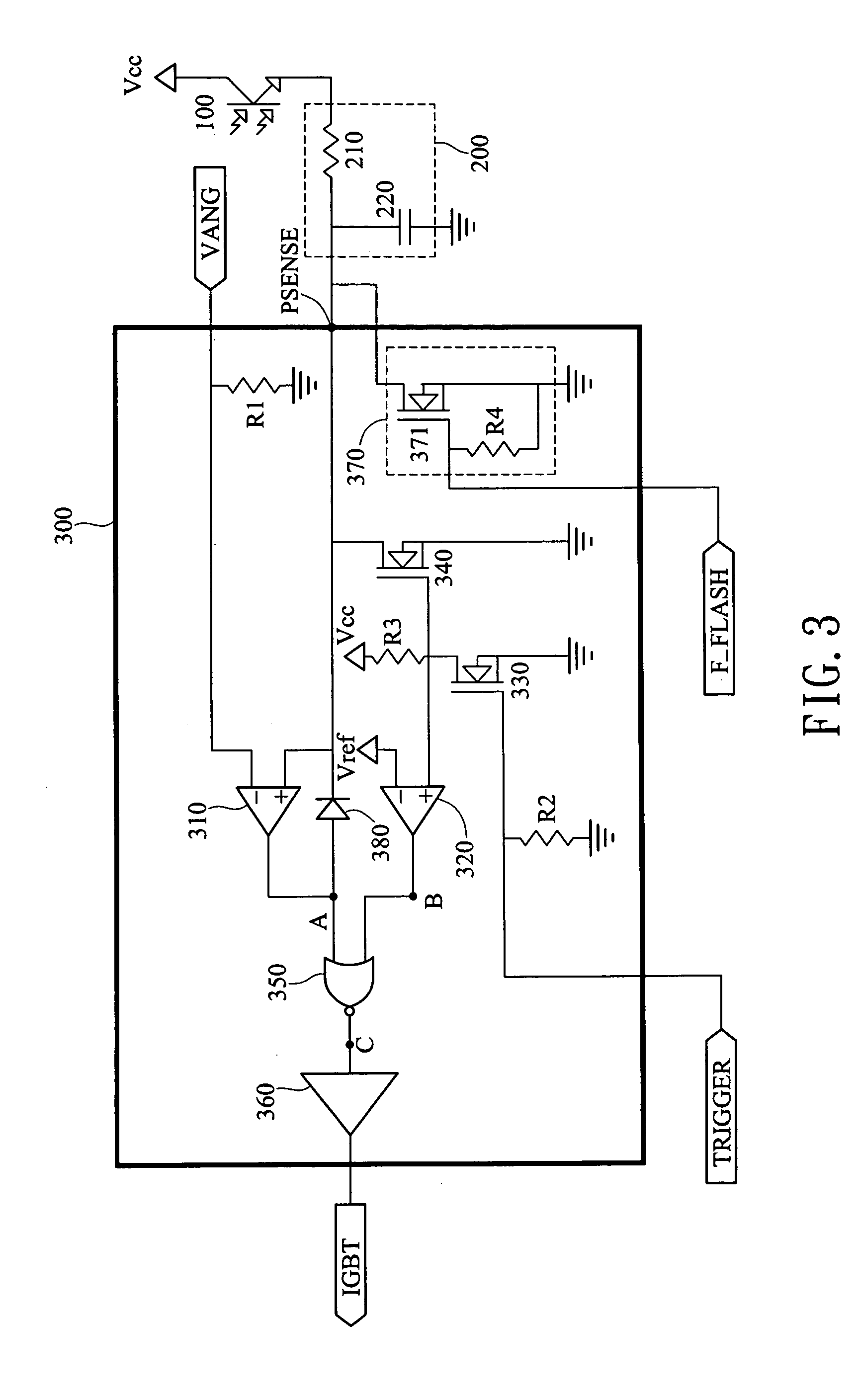
[0049] The operation of the first embodiment according to the invention is described specifically as follows. As illustrated in the drawing, the predetermined voltage set by the second terminal VANG is inputted to the negative input terminal of the first comparator 310, and the positive input terminal of the first comparator 310 is inputted with the sense signal received by the third terminal PSENSE. A reference voltage is input into the negative input terminal of the second comparator 320 and a signal at the drain terminal of the transistor 330 is input into the positive input terminal of the second comparator 320.

[0050] A trigger signal received by the first terminal TRIGGER controls the gate terminal of the first transistor 330. When the trigger signal is at a low level, the first transistor 330 is not turned on while the second transistor 340 is turned on. At that time, the voltage charged in the capacitor 220 discharges to the ground and is thus zero through the second NMOS tra...

second embodiment

[0056] the trigger circuit 300 according to the invention will be described with reference to FIG. 5 in composition and FIG. 6 in timing.

[0057] The embodiment of the trigger circuit 300 comprises a first inverter 410, a first transistor 420, a comparator 440, a first logic gate 550 and a second logic gate 560. The first inverter 410 is used to receive and invert a trigger. The first transistor 420, an NMOS transistor, has a gate terminal connected to the output of the first inverter 410, a drain terminal connected to the negative input of the comparator 440 and a source terminal connected to the ground to form a discharge path when the trigger signal stops. The comparator is used to receive and compare the first comparison signal, the trigger signal and the output luminance voltage with a predetermined voltage to output a first comparison signal. The first logic gate 450 receives the first comparison signal, the trigger signal and the output of the second logic gate 460 to output a ...


PUM


Abstract

A flashlight control circuit is provided to control the flash according to an exposure voltage and a predetermined voltage. Either a first comparator, second comparator and logic gate or a comparator, a first inverter, a first transistor, a first logic gate and a second logic gate may be included in the control circuit. The provided circuit enables the capacitor to discharge promptly when the trigger signal stops. Therefore, an additional control signal for discharge is not necessary. Furthermore, the circuit has a clamping circuit to clamp the exposure voltage at a lower level than the predetermined voltage according to a full flash signal.

Description

[0001] This application claims the benefit of Taiwan Patent Application No. 93110696, filed on Apr. 16, 2004, which is hereby incorporated by reference for all purposes as if fully set forth herein. BACKGROUND OF THE INVENTION [0002] 1. Field of Invention [0003] The invention pertains to a camera flash control circuit and particularly to a flash control circuit with reduced luminance error of a generated flash by use of a phototransistor. [0004] 2. Related Art [0005] With the progress digital image processing technology and charge coupling devices (CCDs), digital cameras have become very important. Since computers have become widely used and other kinds of digital technology are improving rapidly, the digital camera has found itself many more applications. With these advantageous contributions, our daily life is pushed rapidly to become more digitized. [0006] The flash is an indispensable part of a camera. Current flash light operation has a preflash stage and a main flash stage. Th...

Claims


Application Information

Patent Timeline
Patent Type & Authority Applications(United States)
IPC IPC(8): G03B7/16G03B15/03G03B15/05H04N5/235H05B41/32
CPCG03B7/16H05B41/325H04N5/2354G03B15/05G03B2215/0503H04N23/74
Inventor CHU, YI-SHANCHUANG, MING-NAN
Owner IMPRESS ENTERPRISE
Why Eureka
Try Eureka