Transmitter chain timing and transmit power control

a technology of transmitter chain and transmission antenna, which is applied in the direction of gain control, digital transmission, baseband system details, etc., can solve the problems of transmission power problems and difficulties in controlling the amount of transmit power delivered to a transmit antenna, and achieve the effect of changing the overall power gain of the transmit chain

Inactive Publication Date: 2013-02-26
QUALCOMM INC
View PDF20 Cites 25 Cited by
  • Summary
  • Abstract
  • Description
  • Claims
  • Application Information

AI Technical Summary

Benefits of technology

[0007]The power gain change of the second part (for example, the power amplifier part of the transmit chain disposed in a power amplifier integrated circuit) is initiated during the inter-symbol time such that overall transmitted power does not exceed a predetermined amount of transmit power (for example, a maximum transmit power allowed under a communication standard). The power gain change of the second part may, for example, be initiated by the processor of the baseband integrated circuit writing a value to a register which in turn causes a digital signal to be output from terminals of the baseband integrated circuit such that the signal is communicated across dedicated signal conductors to the power amplifier integrated circuit. In one example, the time at which the power gain change of the first part is initiated is separated from the time at which the power gain of the second part is initiated by a substantial amount of time that is at least one quarter of the inter-symbol time. The initiation of the power gain changes of the first and second parts are timed with respect to each other such that the resulting power gain changes of the first and second part occur with a desired timing with respect to each other, and so that the overall power gain of the transmit chain changes in relatively smooth and orderly fashion.

Problems solved by technology

Making the inter-symbol times shorter and shorter in this way may, however, introduce problems including transmit power problems.
In some conditions, difficulties in controlling the amount of transmit power delivered to a transmit antenna may be experienced.

Method used


Image

  • Transmitter chain timing and transmit power control
  • Transmitter chain timing and transmit power control
  • Transmitter chain timing and transmit power control

Examples


Embodiment Construction

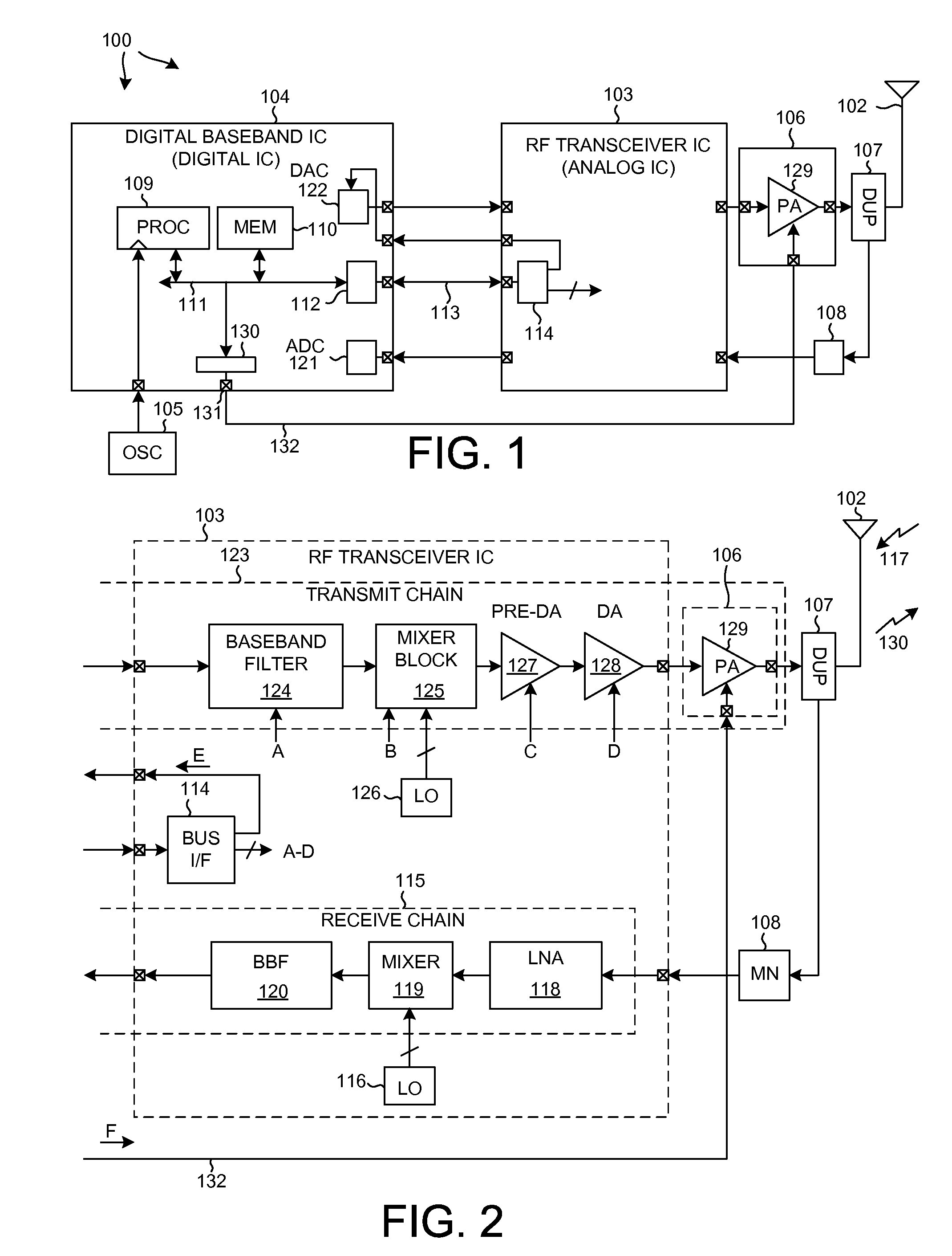
[0018]FIG. 1 is a very simplified high level block diagram of one particular type of mobile communication device 100 in accordance with one novel aspect. The cellular telephone includes (among several other parts not illustrated) an antenna 102, two integrated circuits 103 and 104, an external oscillator 105, an external power amplifier integrated circuit 106, a duplexer 107 and a matching network 108. Integrated circuit 104 is called a “digital baseband integrated circuit” or a “baseband processor integrated circuit”. Digital baseband integrated circuit 104 includes, among other parts not illustrated, a digital processor 109 that executes instructions stored in a processor-readable medium 110. Processor 109 can cause information to be communicated across parallel local bus 111 and serial bus interface 112 and serial bus conductors 113 to serial bus interface 114 of integrated circuit 103. Processor 109 is clocked by a clock signal received from external oscillator 105. Integrated c...


PUM


Abstract

In a communications system, transmitter power gain can be changed between symbols. A power gain change of a first part of a transmit chain is initiated a first time, whereas a power gain change of a second part of the transmit chain is initiated at a second time, such that the resulting power gain changes of the first and second parts both occur substantially within an inter-symbol time in a desired relationship to one another. In one example, the power gain change of the first part is initiated before the beginning of the inter-symbol time to account for expected serial bus latency between initiation and execution of the power gain change of the first part. The power gain change of the second part is initiated during the inter-symbol time such that overall power does not exceed an amount (for example, a maximum permitted under a communication standard).

Description

CROSS-REFERENCE TO RELATED APPLICATION[0001]This application claims the benefit under 35 U.S.C. §119 of Provisional Application Ser. No. 61 / 040,656, filed Mar. 29, 2008, said provisional application is incorporated herein by reference.BACKGROUND INFORMATION[0002]1. Technical Field[0003]The present disclosure relates to the discrete timing and power gain control of multiple different parts of a transmitter chain.[0004]2. Background Information[0005]Wireless communication protocols and standards often involve the sending of information in a sequence of discrete bit times or symbols. As data rates have increased over the years, the duration of such bit times or symbols has become shorter. In some communication protocols today, a symbol includes a data communication time portion, as well as a first guard time that precedes the data communication time portion and a second guard time that follows the data communication time portion. Multiple such symbols are transmitted rapidly in back-to...

Claims


Application Information

Patent Timeline
Patent Type & Authority Patents(United States)
IPC IPC(8): H04L25/49
CPCH03G3/3042
Inventor KADOUS, TAMER A.GEORGE, BRIAN M.WANG, JIBING
Owner QUALCOMM INC
Why Eureka
Try Eureka