Power adjusting device for dust collector

A technology for power regulation and vacuum cleaners, which is applied in the installation of electrical equipment, etc., can solve problems such as endangering the safety of operators, inconvenient operation for users, and difficulty in determining the power level, so as to improve safety, improve convenience and performance, and reduce demand. the effect of the space

Inactive Publication Date: 2010-11-17
LG ELECTRONICS (TIANJIN) APPLIANCES CO LTD
View PDF1 Cites 7 Cited by
  • Summary
  • Abstract
  • Description
  • Claims
  • Application Information

AI Technical Summary

Problems solved by technology

[0011] However, this kind of knob is completely exposed, and it is easy to be pulled out due to careless touch. At this time, the circuit board on the knob shaft will be exposed. Because the circuit board is of high voltage, it will endanger the safety of the operator in case of electric leakage.
[0012] Moreover, in the specific operation, when changing the power of the vacuum cleaner, the customer needs to bend down and operate by hand, which causes inconvenience to the user.
[0013] In addition, the exposed knob plate will wear out the power indicator characters during use, and it is difficult for users to determine the current power level during use.

Method used


Image

  • Power adjusting device for dust collector
  • Power adjusting device for dust collector
  • Power adjusting device for dust collector

Examples


Embodiment Construction

[0030] Below in conjunction with accompanying drawing and specific embodiment the present invention is described in further detail:

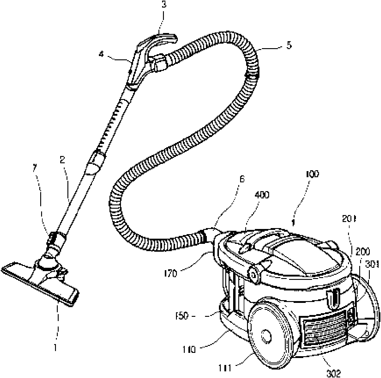
[0031] The working principle of the vacuum cleaner of the present invention is the same as that of the prior art, and the prior art can be referred to, so it will not be described again, and the same symbols as those of the prior art will be used. The differences between the present invention and the prior art will be described below Detailed explanation:

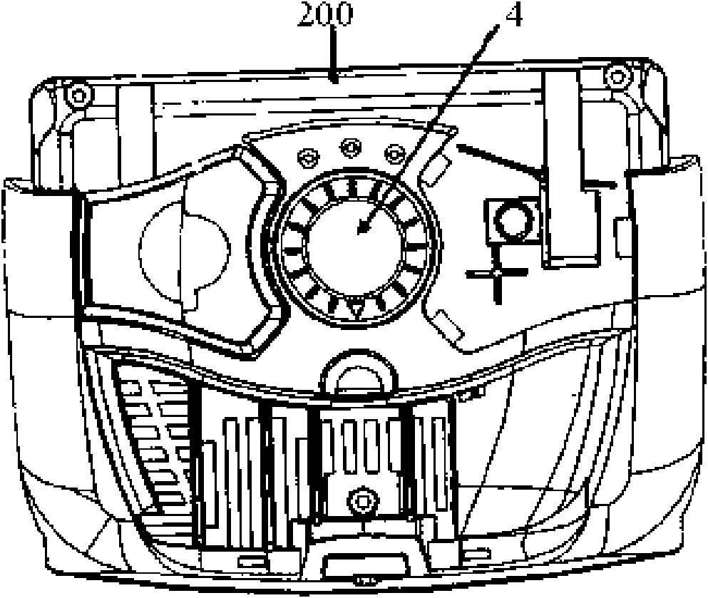
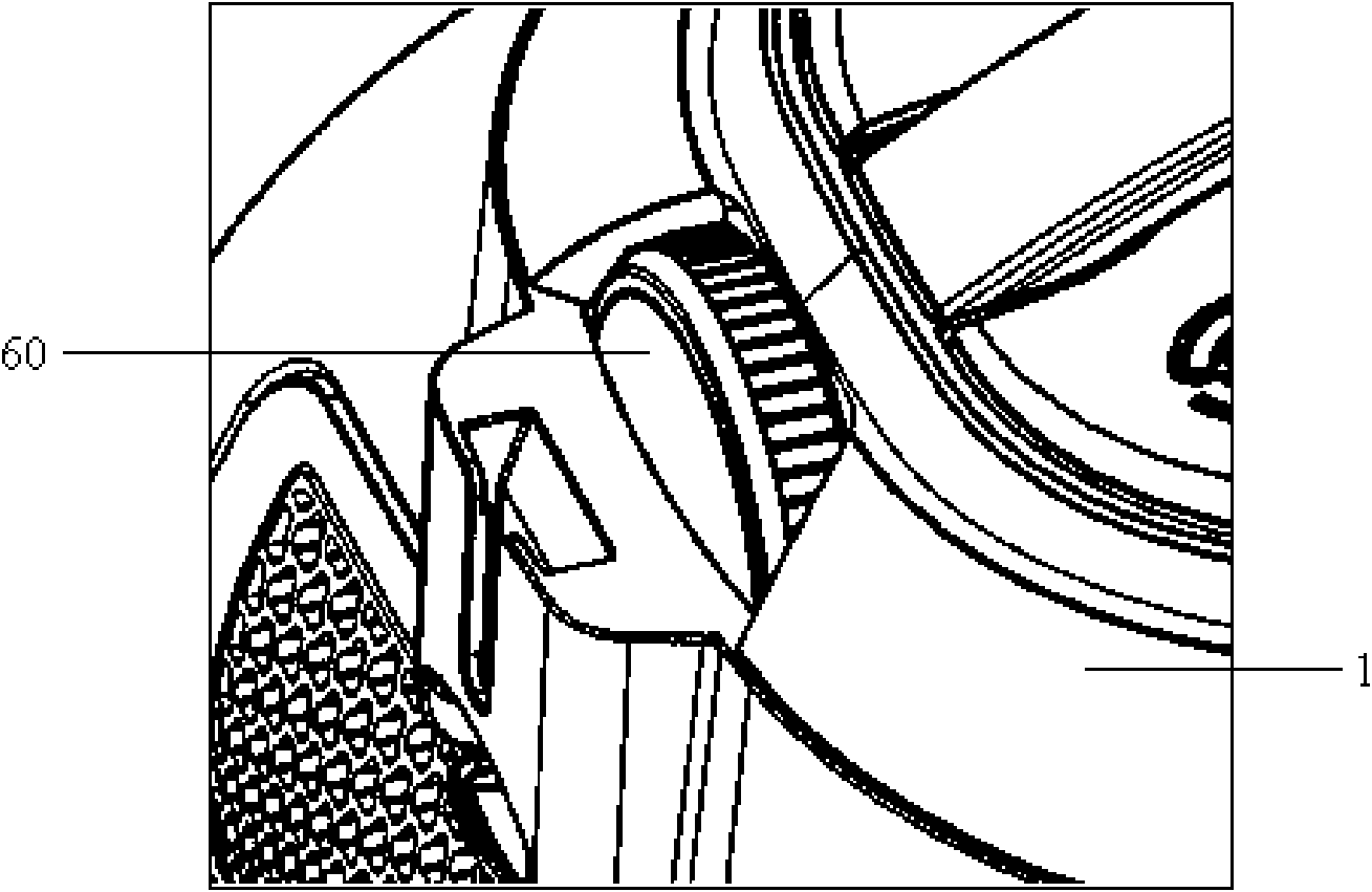
[0032] Such as Figure 3 to Figure 5 As shown, the power control device 60 of the vacuum cleaner is provided on the side of the tail of the body 1 of the vacuum cleaner, which is composed of a knob 61 perpendicular to the ground, a support member 62 and a rotary sliding rheostat 65 coaxially arranged with the knob 61. . The knob 61 with a larger diameter is made of hard insulating material and has a certain thickness. For the convenience of the user, the knob 61 can be easily rotated with t...


PUM


Abstract

The invention discloses a power adjusting device for a dust collector, which is used for adjusting the power of the dust collector to meet the requirements of different occasions on suction. The power adjusting device consists of a knob, a knob bracket and a rheostat connected with the knob, wherein the power adjusting device is arranged on the side part of a dust collector body; and only a part of the knob is exposed outside the dust collector body. The power adjusting device can allow a user to optionally, conveniently and continuously change the power of the dust collector so as to meet the requirements of different places on the suction of the dust collector, and reduces a needed space, enhances touch effect, improves use convenience, simultaneously increases the rotation radius of the knob and enhances use safety.

Description

technical field [0001] The invention relates to a vacuum cleaner, in particular to an adjusting device for controlling the power of the vacuum cleaner. Background technique [0002] Generally, a vacuum cleaner is a device that uses a vacuum to generate suction to inhale air, make the air flow through various filters, filter foreign objects in the air, and clean the room. [0003] figure 1 It is a perspective view of a prior art vacuum cleaner. Such as figure 1 As shown, it includes: a fuselage 100 ; a suction pipeline connected to the suction side of the fuselage 100 . A fan and a dust collection unit 400 are provided inside the body 100 to send clean air to the outside after filtering out foreign objects in the air. [0004] The suction line is a line for sucking in air and foreign matter using the suction force of the body 100 . Specifically, the suction pipeline includes: a suction nozzle 1 that uses a strong air flow to inhale air containing foreign matter from the ...

Claims


Application Information

Patent Timeline
Patent Type & Authority Applications(China)
IPC IPC(8): A47L9/28
Inventor 王力伟
Owner LG ELECTRONICS (TIANJIN) APPLIANCES CO LTD
Why Eureka
Try Eureka