Tinted semi-finished lens having impact resistance and method for manufacturing the same

a semi-finished, lens technology, applied in the field of semi-finished lenses, can solve the problems of deformation and distortion difficulty in adhesion between the two layers, and variation in the effects of the opposing layer, so as to achieve the effect of reducing the tendency, reducing the power of the lens, and being easily broken

Active Publication Date: 2011-03-17
MIYOSHI INDAL ENTERPRISE
View PDF1 Cites 7 Cited by
  • Summary
  • Abstract
  • Description
  • Claims
  • Application Information

AI Technical Summary

Benefits of technology

[0011]Commonly, when the semi-finished lens is processed to have a minus power, as shown in FIG. 10B, the center thickness is defined to be 1.6 mm or more. The reason for this is that a lens having a center thickness of less than 1.6 mm deforms to change the lens power or to be readily broken. While, when the lens is processed to have a plus power, as shown in FIG. 10C, the lens is required to have an edge thickness of 1.6 to 1.7 mm or more for Nylol or of 2 mm or more for full rim frames. Thus, in each case, the lens thickness after polishing is 1.6 mm or more. According to a method in which the tinted layer is uniformly formed within the thickness and a layer for lens power or the like is arranged on the back side of the tinted layer, even when the back layer is polished to the maximum extent by polishing, the tinted layer is not polished, and therefore the tinted layer remains in its original form and the lens can provide the lens power.
[0012]Furthermore, as for the density of the tinted layer, when the tinted layer has a uniform thickness in a horizontal direction (FIG. 5), that is, when the curvature radii are (R1)=(R2), the tint densities are the same from the lens upper part to the lower part even when the lens is viewed from any direction. However, the lens obtains a plus power because the center has a different lens thickness from the periphery. The lens power can be adjusted in the transparent layer on the back side of the tinted layer. However, only a uniform density of the tinted layer should not be essentially required, but a lens shown in FIG. 4 is preferred because it does not affect the lens power. Each of the lenses in FIG. 4 has a uniform lens thickness of 1.5 mm and the difference between the curvature radii is the lens thickness t. In this case, the lens has a uniform lens thickness of 1.5 mm at any position but obtains a minus lens power because of the different curvature radii between the front face and the back face. As shown in Fig., a beam that enters from a horizontal direction is refracted to the lens center direction when the beam enters the lens, then goes slightly to the lens center direction, and goes back to the horizontal direction again when the beam goes out from the back face of the lens. Accordingly, the difference of the tint density between the center and the edge (the uppermost part of the lens and the lowest part of the lens) is reduced in the external appearance. In each lens having a small curve (FIG. 4(a) and FIG. 5(a)), the tendency is further reduced. A lens that not only requires the uniform density of the tinted layer but does not affect the lens power is between the lenses in FIG. 4 and FIG. 5. However, because such lens has a thin thickness of 1.5 mm or less, any lens between the lenses in FIG. 4 and FIG. 5 obtains a lens power without any problem.
[0013]A tinted lens is often once removed from a mold and then inserted in another mold. In this case, because a clearance is readily generated between the convex mold and the molded product having a thickness of 1.5 mm by molding shrinkage and the like and a curved surface of lens is not formed easily, this method can be adopted into high-mix low-volume production. The flow chart of the manufacturing process is shown in FIG. 6(a).
[0014]Conversely, as shown in FIGS. 7 and 8, when the tinted lens or the transparent layer is not removed from the mold after molding and then molded as is with an interchanged convex mold or concave mold, a clearance is not generated between the molded product and the mold and a stable curve can be generated. The flow chart of the manufacturing process is shown in FIG. 6(b).
[0015]The flow length of a commonly used resin affects the impact resistance. A resin having a large molecular weight has a short flow length and low flow ability and thus has excellent impact resistance but poor mold ability (readily generates distortion). In contrast, a resin having a small molecular weight has a long flow length and high flow ability and thus has good mold ability (generates less distortion) but poor impact resistance.
[0016]As used herein, “impact resistance” means that, in the drop ball test according to ANSI (American National Standard Institute), when an iron ball is dropped to a lens shaped sample having a center thickness of 1.8 to 2 mm, fragments are not scattered from the impacted lens. In the test, the ball has a weight of 111.6 g (4 oz) and more preferably has a weight of 198 g (7 oz).

Problems solved by technology

Furthermore, when two different resins are used, the adhesion between both layers sometimes has trouble.
Moreover, in the manufacturing process of both layers, the layers having different thicknesses cause a problem in which, depending on the order of layer formation, effects to the opposing layer, such as deformation and distortion, vary.
In particular, when the former layer is thin and the amount of the latter flowed resin is large, the former layer readily melts and flows to cause the distortion.

Method used


Image

  • Tinted semi-finished lens having impact resistance and method for manufacturing the same
  • Tinted semi-finished lens having impact resistance and method for manufacturing the same
  • Tinted semi-finished lens having impact resistance and method for manufacturing the same

Examples


example 1

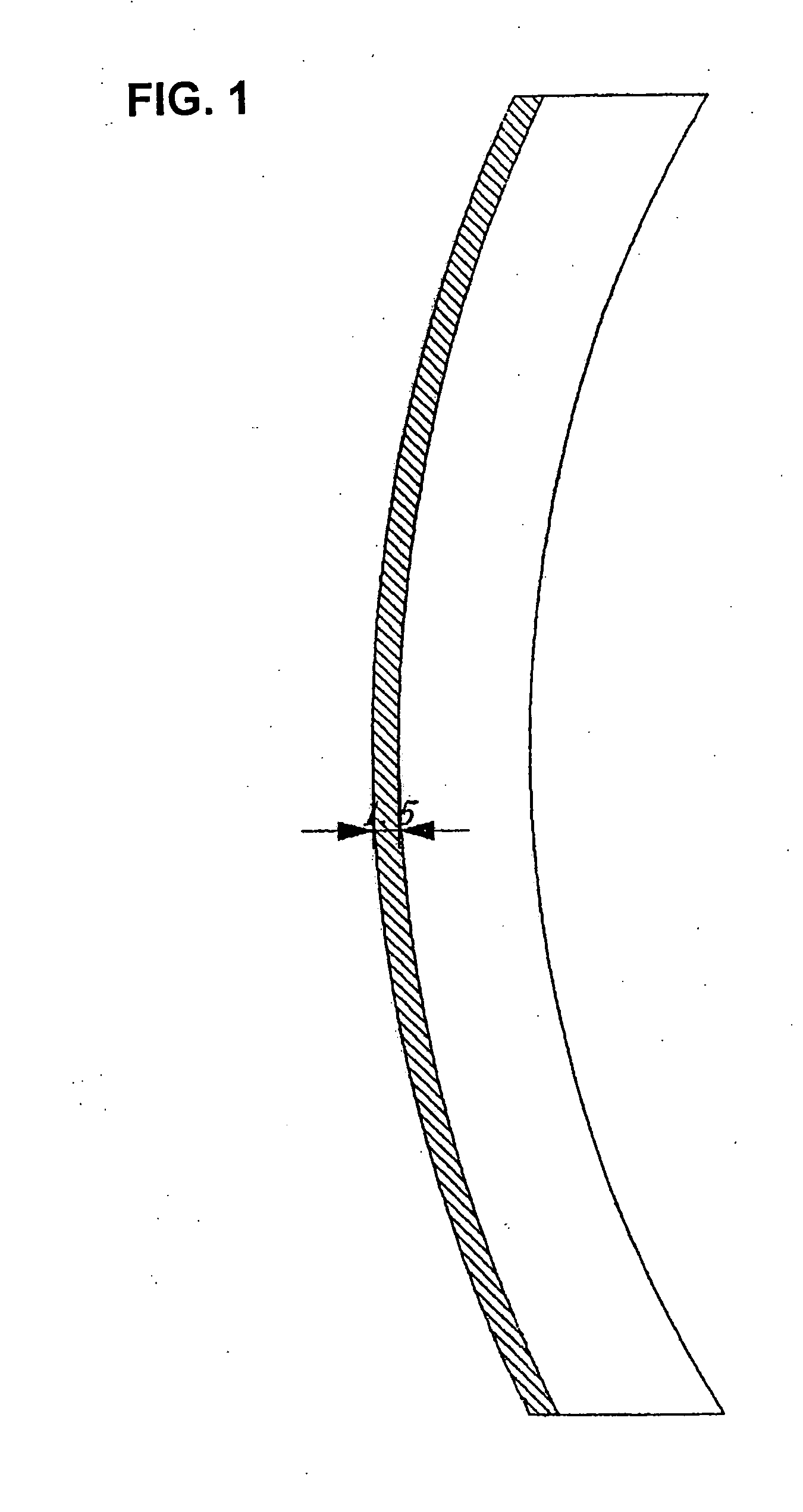
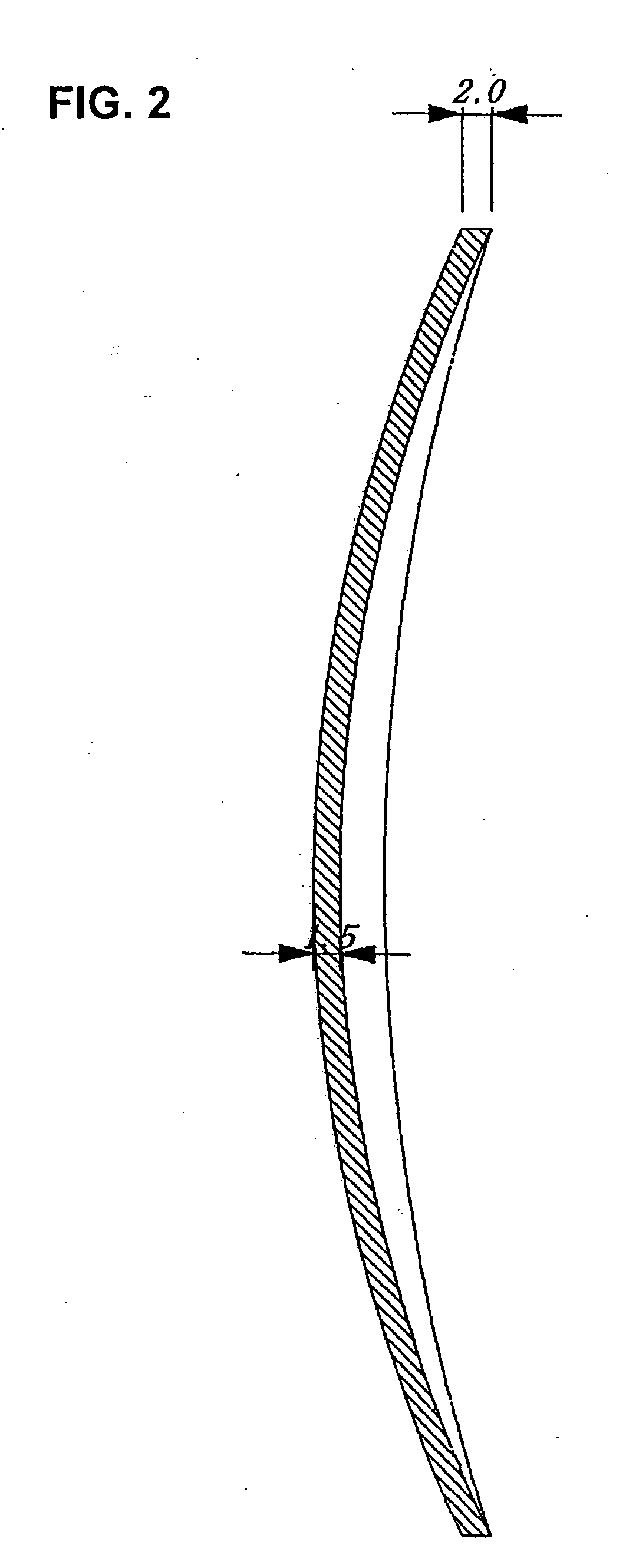
[0036]Example 1 of the invention will be described with reference to FIG. 1 and FIG. 2.

[0037]Polycarbonate (a molecular weight of 17,000) colored with black ink color having a transmission factor of 25% when the front curve was 8R (a curvature radius of 66.25 mm), the back curve was 8.2R (a curvature radius of 64.75 mm), and the center thickness was 1.5 mm was molded at a resin temperature of 300° C. with a mold at 110° C. to give a tinted molded product having a thickness of 1.5 mm and little distortion.

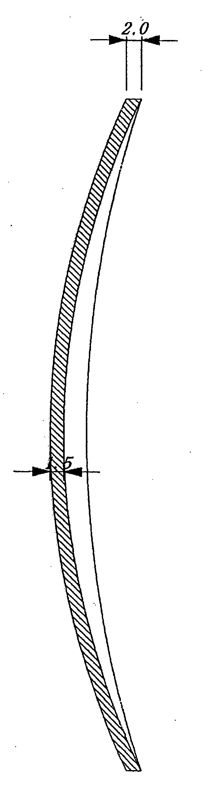
[0038]The obtained molded product was inserted into a concave mold, and to the back side a transparent polycarbonate (a molecular weight of 22,000) layer having a thickness of 8 mm was formed to give a semi-finished lens shown in FIG. 1.

[0039]The semi-finished lens obtained in this manner was cut and polished to make a plus power lens having a center thickness of 4.6 mm and a curvature radius of the back curve of 105 mm (5.04R), and then the lens periphery was processed to make a le...

example 2

[0041]The drop ball test according to ANSI (American National Standard Institute) was performed on the obtained lens (an iron ball with a weight of 7 oz was dropped from a height of 50.0 in. to examine fragment scattering due to lens cracking). As a result, the fragment scattering was not observed to prove the impact resistance. In contrast, when the drop ball test was performed on the tinted layer having a thickness of 1.5 mm alone, the fragments were scattered.

[0042]Example 2 of the present invention will be described with reference to FIG. 1, FIG. 3, and FIG. 7. The efficient method for manufacturing two molded products when two sets of cavity and core molds were prepared for molding will be described in detail in Example 3 with reference to FIG. 8.

[0043]Polycarbonate (a molecular weight of 17,000) colored with black ink color having a transmission factor of 25% when the front curve was 8R (a curvature radius of 66.25 mm), the back curve was 8R (a curvature radius of 64.75 mm), a...

example 3

[0048]Example 3 of the present invention will be described with reference to FIG. 8.

[0049]The method can efficiently provide a lens that has the least distortion and deformation. The method employing two sets of cavity and core molds will be described. The following processes 1) to 6) correspond to the processes in the drawing.

[0050]1) Two sets of cavity and core molds for molding were prepared. Each core mold had the same shape in the lens molding part (corresponding to the back face of the lens). The second cavity mold has a larger sprue-runner (1) for pouring resin than the first cavity mold to keep the flow pass for a colored resin. In addition, the second cavity mold had the lens molding part (corresponding to the front face of the lens) that has the same curve as in the first cavity mold and is placed 1.5 mm backward comparing with that in the first cavity mold. (In Fig., the broken lines (2) show the larger part than the first cavity mold)

[0051]2) to 3) The core mold and the ...


PUM

PropertyMeasurementUnit
thicknessaaaaaaaaaa
thicknessaaaaaaaaaa
edge thicknessaaaaaaaaaa

Abstract

Provided is a method for manufacturing a tinted semi-finished lens that uses polycarbonate, has high light shielding effect, has impact resistance even after polishing, and can have a uniform tint. In particular, in order to provide a tinted semi-finished lens that has the same light shielding at the lens center and the lens edge when a wearer looks through the tinted lens, and furthermore, that seems to have the same light shielding when a third party looks at the wearer, a tinted layer having a uniform thickness and a transparent layer on the back side are integrally formed. Furthermore, in order to provide the impact resistance to either of the resins included in the layers, a low flow resin having a large molecular weight and a short flow length is used. In order to minimize lens distortion and to provide the impact resistance to the lens, the transparent layer employs a resin having the impact resistance, and the transparent layer is formed first and then the tinted layer is formed as an additional layer. Moreover, provided is a method for simultaneously manufacturing two sets of tinted lenses. In the method, two sets of molds are used, a first molded product is obtained in one of the two sets of the molds, and then is transferred to the other mold to form a second molded product, and simultaneously, another first molded product is molded in the first mold.

Description

FIELD OF THE INVENTION[0001]The present invention relates to a tinted semi-finished lens that has color shade not involving a change in the external appearance, does not have uneven tint when the lens is used, and has impact resistance, even when the lens is polished for lens power. Moreover, the present invention relates to a method for manufacturing a tinted semi-finished lens with a little distortion for stable lens characteristics.BACKGROUND OF THE INVENTION[0002]Semi-finished lenses using thermoplastic resins save cost and time for the molding and thus are useful. In particular, the polycarbonate semi-finished lenses having impact resistance can resist the impact by a foreign object to protect the eyeballs when the eyeglass frame is worn and thus are useful.[0003]As the thermoplastic resins other than the polycarbonate, polyamide, modified polycarbonate-polyester, thermoplastic polyurethane, and the like also have the impact resistance and thus are suitable. Furthermore, in the...

Claims


Application Information

Patent Timeline
Patent Type & Authority Applications(United States)
IPC IPC(8): G02C7/10B29D11/00
CPCG02C2202/16G02C7/108
Inventor MIYOSHI, KAZUYUKI
Owner MIYOSHI INDAL ENTERPRISE
Why Eureka
Try Eureka