Catalytic burner apparatus for Stirling Engine

a technology of catalytic burner and stirling engine, which is applied in the direction of lighting and heating apparatus, machines/engines, indirect heat exchangers, etc., can solve the problems of enhancing the efficiency of the operation of the stirling engine, requiring an external heat source to operate, and still exists in the art in the field of stirling engine enhancement efficiency, etc., to achieve enhanced transport properties, avoid boundary layer buildup, and increase the reactivity area

Active Publication Date: 2013-03-05
PRECISION COMBUSTION
View PDF28 Cites 9 Cited by
  • Summary
  • Abstract
  • Description
  • Claims
  • Application Information

AI Technical Summary

Benefits of technology

[0047]It has now been found that a catalytic reactor comprising catalyst deposited on ultra-short-channel-length metal elements (substrate), known in a preferred embodiment as Microlith® brand ultra-short-channel-length metal mesh catalyst, which is commercially available from Precision Combustion, Inc., located in North Haven, Conn., efficiently and effectively generates heat as a burner within the operative constraints for a Stirling Engine known within the art. More importantly and in contrast to the prior art, the catalytic reactor comprising said catalyst, more preferably comprising one or more noble metals deposited on Microlith® brand ultra-short-channel-length metal mesh elements, is positioned in the apparatus of this invention in direct communication (i.e., in direct contact with, that is, non spaced-apart relation) with the heater head thereby providing heat transfer by thermal conduction, the most efficient manner of heat transfer in Stirling Engine applications.
[0049]The preferred Microlith® brand ultra-short-channel-length metal mesh design promotes the packing of more active area into a small volume, providing increased reactivity area for a given pressure drop. Whereas in a conventional honeycomb monolith having conventional long channels, a fully developed boundary layer is present over a considerable length of the device; in contrast, the ultra-short-channel-length characteristic of the Microlith® brand substrate avoids boundary layer buildup. Since heat and mass transfer coefficients depend on the boundary layer thickness, avoiding boundary layer buildup enhances transport properties. The advantages of employing Microlith® brand ultra-short-channel-length metal mesh as a substrate to control and limit the development of a boundary layer of a fluid passing therethrough is described in U.S. patent application Ser. No. 10 / 832,055 which is a Continuation-In-Part of U.S. Pat. No. 6,746,657 to Castaldi, both incorporated in their entirety herein.
[0050]In one embodiment of the present invention (FIG. 6), a catalytic reactor (18) comprising a catalytically reactive Microlith® brand ultra-short-channel-length metal mesh is positioned in direct contact with heat exchanger fins (64) brazed onto the heater head (20). In this embodiment, the heat exchanger fins form an integral part of the heater head; and thus the metal mesh is in contact with (i.e., not spaced-apart from) thermally conductive walls of said heater head. Use of the catalytically reactive Microlith® brand ultra-short-channel-length metal mesh in this manner provides for: rapid catalytic light-off; excellent robustness for different fueling rates; and easy replacement of the catalytic reactor burner section of the Stirling Engine.
[0051]The thermally conductive walls of the catalytic reactor minimize the potential for overheating of the catalyst even at equivalence ratios near 1.0, where the term “equivalence ratio” is defined as the ratio of the actual mole ratio of fuel to oxidant combusted relative to the stoichiometric mole ratio of the fuel to oxidant for the combustion reaction (i.e., the mole ratio of fuel to oxidant for complete conversion of the fuel to CO2 and H2O). Energy, in the form of heat, is rapidly extracted from the catalytic fuel oxidation zone predominantly via thermal conduction from the catalyst to the heater head. Heat transfer via convection of combustion gases and radiation from the heated catalyst may also contribute to overall heat transfer.

Problems solved by technology

Stirling Engines, however, require an external heat source to operate.
However, a problem still exists in the art with respect to enhancing the efficiency of the operation of a Stirling Engine.
As recognized by one skilled in the art, the uniform burning of a matrix burner element remains a problem.
Unfortunately, the solution offered by Bohn still is too complex and inefficient for desired uses.
Clark teaches that a problem still exists in the art with respect to the effective and efficient transfer of heat to a Stirling Engine heater head as late as 2003.
Another problem with burner devices for a Stirling Engine is described in U.S. Pat. No. 6,513,326 to Maceda, et al.
According to Maceda, heat is not uniformly distributed to the working gas within the heater tubes because a single burner device is used to generate and effectuate the heat transfer.
Unfortunately, the solution offered by Maceda still is too complex and inefficient for desired uses.
The Langenfeld apparatus and method suffer from the same inefficient transfer of heat (via gas convection and flame radiation) as found in the previously described art.

Method used


Image

  • Catalytic burner apparatus for Stirling Engine
  • Catalytic burner apparatus for Stirling Engine
  • Catalytic burner apparatus for Stirling Engine

Examples


Embodiment Construction

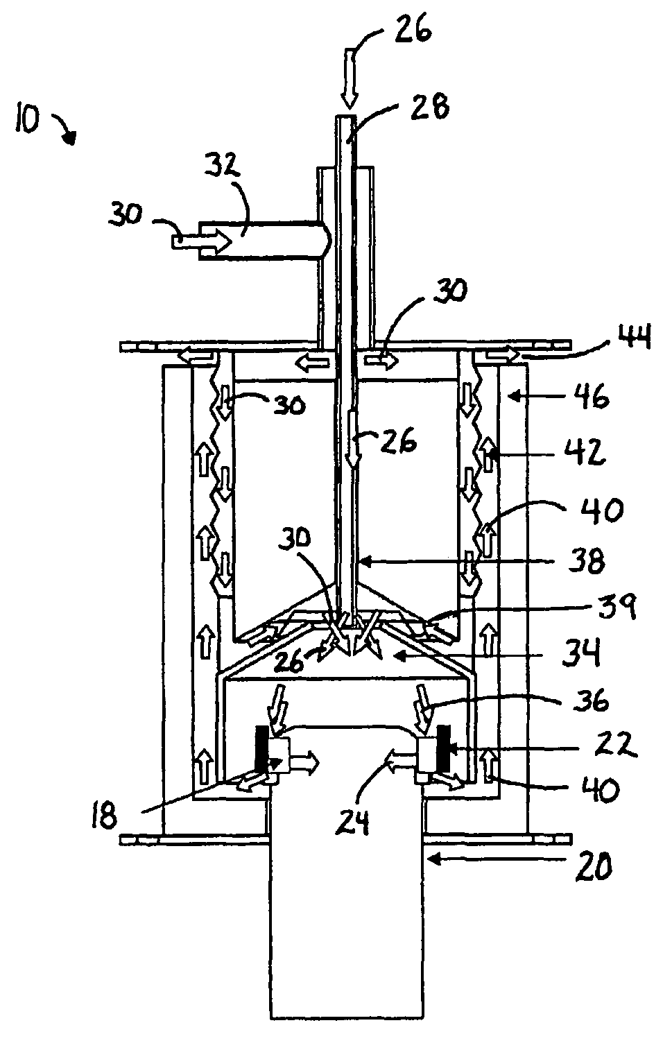
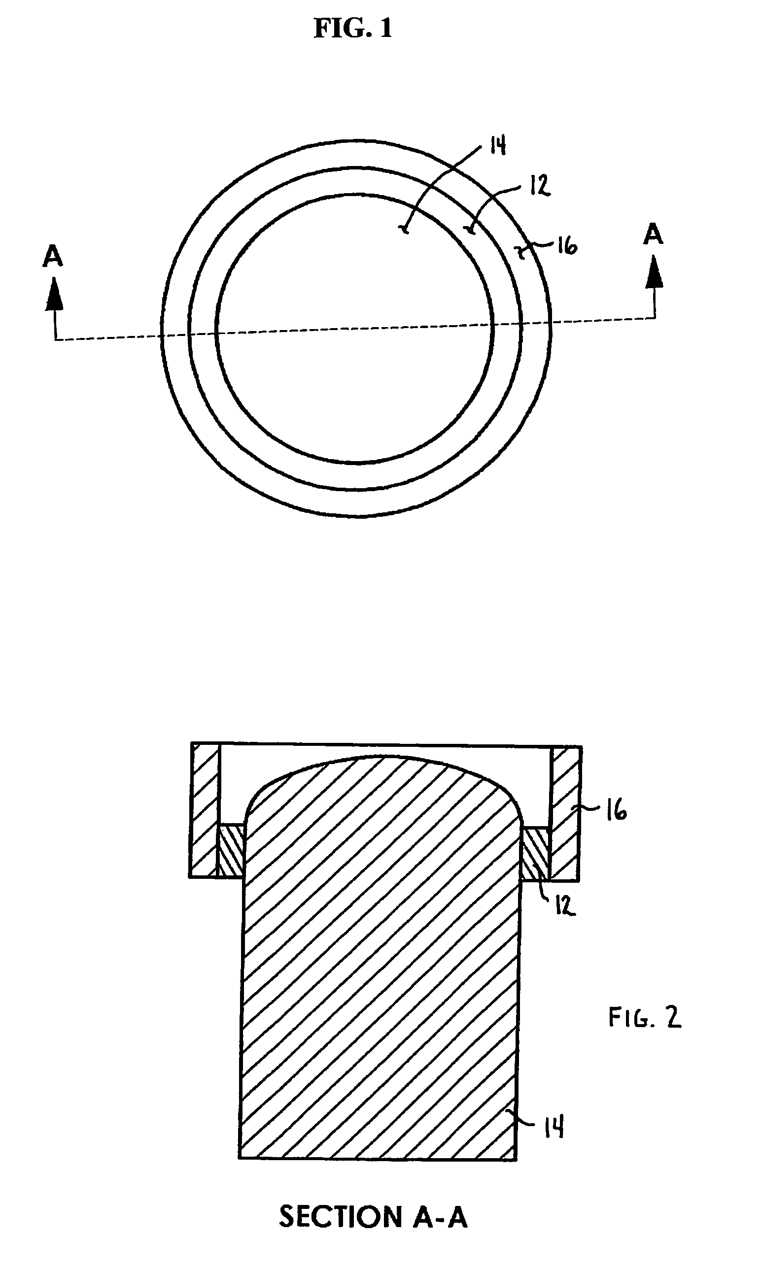
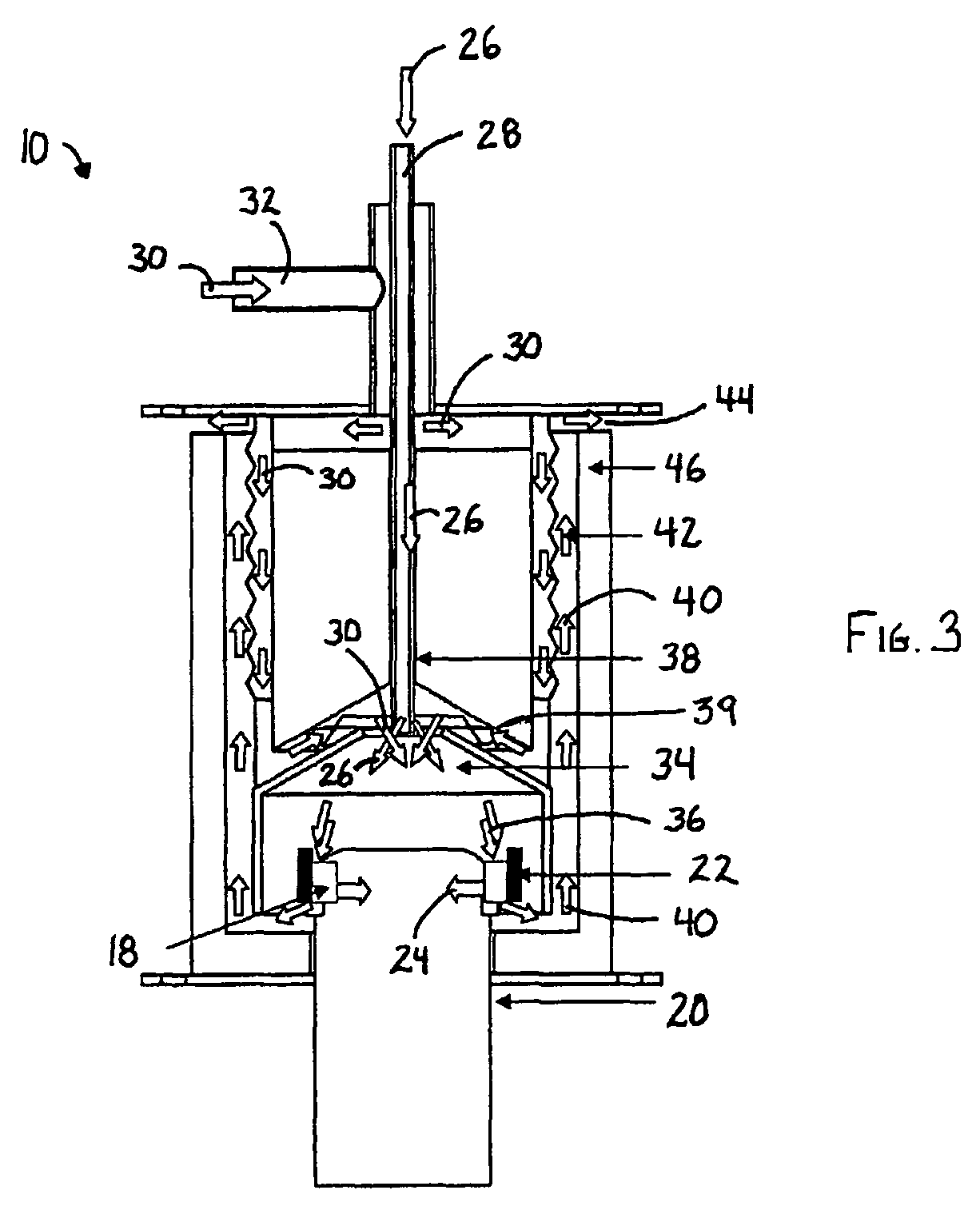
[0066]In a preferred aspect, the present invention provides a simple, efficient and effective catalytic reactor apparatus for generating heat and transferring the heat via conduction to the heater head of an external combustion engine. The apparatus comprises:[0067](a) a combustor into which is internally secured a heater head of an external combustion engine, the combustor comprising a chamber for mixing fuel and air;[0068](b) a fuel injection path for feeding a liquid fuel into the chamber;[0069](c) an air injection path for feeding air into the chamber;[0070](d) a catalytic reactor in direct contact with the heater head, the catalytic reactor comprising a catalyst deposited on ultra-short-length-channel metal elements;[0071](e) an igniter for lighting off the catalyst and thus initiating flameless combustion of the fuel with air; and[0072](f) an outlet port for exhausting combustion gases.

[0073]In another preferred aspect, this invention comprises an external combustion engine ha...


PUM


Abstract

The invention provides an apparatus and a method for transferring heat by conduction to the internal heat acceptor of an external combustion engine. Fuel and air are introduced into a combustion chamber and mixed to form an air / fuel mixture. The air / fuel mixture is directed into a catalytic reactor that is positioned in direct contact (non-spaced-apart relation) with the heater head. Heat is transferred via conduction from the catalytic reactor to the heater head; and the catalytic reaction products are exhausted with heat recuperation.

Description

CROSS-REFERENCE[0001]This application is a continuation-in-part of U.S. patent application Ser. No. 11 / 803,464, filed May 14, 2007 now U.S. Pat. No. 7,913,484, which claims the benefit of U.S. Provisional Application No. 60 / 799,857, filed May 13, 2006. This application is a continuation-in-part of U.S. patent application Ser. No. 11 / 803,464, filed May 14, 2007, which is also a continuation-in-part of U.S. patent application Ser. No. 11 / 364,402, filed Feb. 28, 2006 now abandoned. The aforementioned priority applications are incorporated herein in their entirety by reference.GOVERNMENT RIGHTS[0002]This invention was made with government support under U.S. Contract No. W911-NF-04-1-0238, Subaward No. Y-04-0023. The U.S. government holds certain rights in this invention.FIELD OF THE INVENTION[0003]The present invention is generally directed to an apparatus for providing heat to an external combustion engine. In particular, the present invention is directed toward providing substantially...

Claims


Application Information

Patent Timeline
Patent Type & Authority Patents(United States)
IPC IPC(8): F01B29/10
CPCF02G1/043F02G1/055F02G2254/70
Inventor ROYCHOUDHURY, SUBIRSPENCE, DAVIDCROWDER, BRUCE B.MASTANDUNO, RICHARD T.BERRY, JONATHAN
Owner PRECISION COMBUSTION
Why Eureka
Try Eureka