Continuously variable transmission

a transmission and variable technology, applied in the field of transmission, can solve the problems of affecting the transmission quality of the transmission device, the operation process is quite complicated, and the speed variation is relatively long, and achieves the effect of reducing friction

Active Publication Date: 2013-03-05
MAK MIU LING
View PDF5 Cites 0 Cited by
  • Summary
  • Abstract
  • Description
  • Claims
  • Application Information

AI Technical Summary

Benefits of technology

[0006]An object of the present invention is to provide a continuously variable transmission capable of a smooth and continuous variation of an input and output transmission ratio thereof. The continuously variable transmission has its operation completely different from the conventional transmissions which transmit power through friction. The transmission of the invention allows to minimize the friction during the transmission of the power of its drive wheel.
[0036]In summary, the continuously variable transmission of the present invention adopts a drive wheel, an endless sleeve, a ring wheel, at least one linking member, and wedge teeth or the like in specific forms of configuration. The drive wheel is provide with an annular recess, in which a plurality of reversal wedge teeth run, and the wedge teeth are connected with a head portion of the linking member with its linking portion connected with the ring wheel, and the spread of axles between the drive wheel and the ring wheel is adjusted via the swinging of the endless sleeve. By means of the power of the drive wheel and with the aid of the locking and releasing operations of the wedge teeth, the linking members are urged to drive the ring wheel to change the input and output transmission ratio. The transmission ratio could generally reach up to 1:1-1:5 or above. The change of the transmission ratio can be performed during the travelling of the vehicle to provide a continuously variable speed variation, with the result of a smooth ride and a reduction in fuel. The continuously variable transmission is preferably adapted for use in a bicycle, wherein the spread of axles between the ring wheel and the drive wheel is adjusted by regulating a wire, such that the magnitude of speed variation is not restricted, the variation range of the transmission ratio is large, and the power could be synchronously input during the speed variation. Thus, the transmission of the invention has the advantages of being simple in structure, easy in operation, low in noise and abrasion, small in energy loss and great in variation effect.

Problems solved by technology

For example, a manual or an automatic transmission for a motor vehicle may provide a 4- to 5-speed transmission, in which each speed section needs to shift in a stepped manner, namely to shift from an upper section to a lower section and then from the lower section to a next section, such an operation process would be quite complicated, and sometimes a momentary failure might occur during the shifting process.
As far as a simple transmission for a bicycle is concerned, this transmission adopts usually a so-called conical pulley having a plurality of chain wheels of diameters varying in magnitude sequentially, the transferring of the chain among various chain wheels is quite unsmooth, resulting in a relatively long time for speed variation, and a failure might occasionally occur.
This type of transmission has advantages of being simple in structure and easy in speed variation; but both ends of the belt are subject to a huge friction during operation, such that the belt is continuously bent and straightened to an extent, and thus prone to wearout and outbreak, even energy loss.
Such a belt-type continuously variable transmission is not suitable for use in motor vehicles having a large horsepower.

Method used


Image

  • Continuously variable transmission
  • Continuously variable transmission
  • Continuously variable transmission

Examples


first embodiment

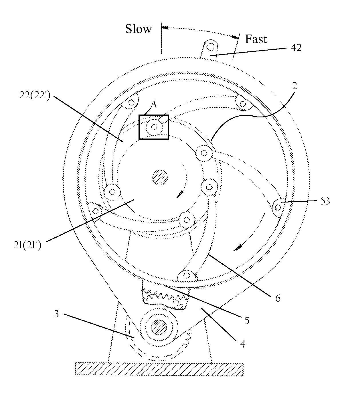
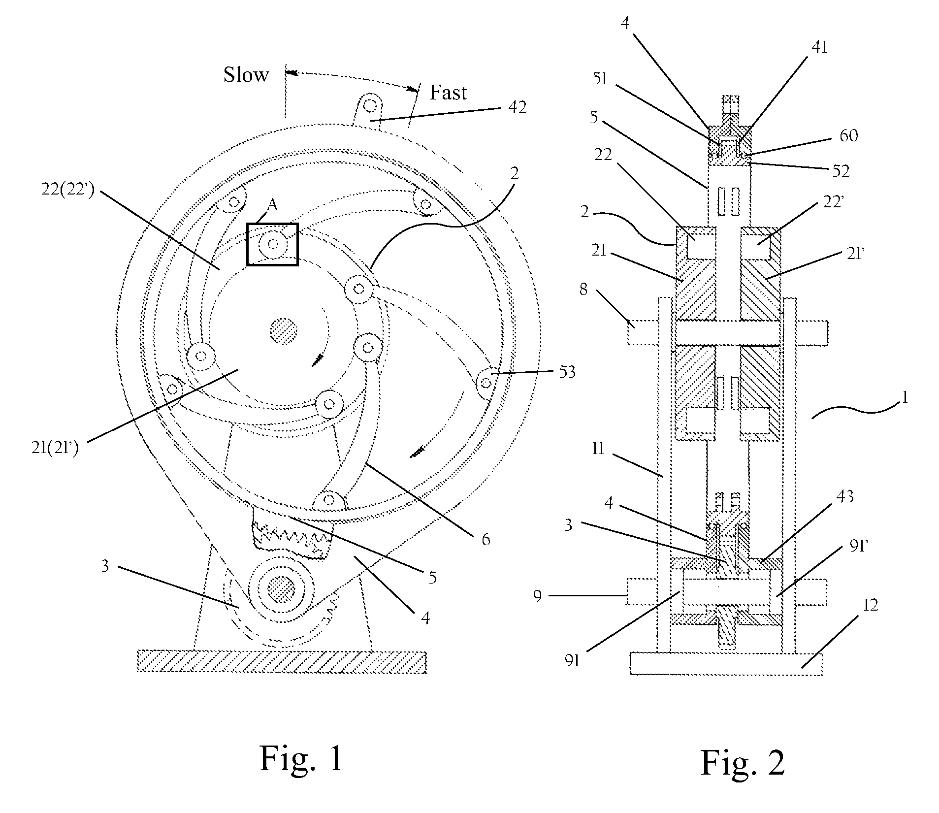
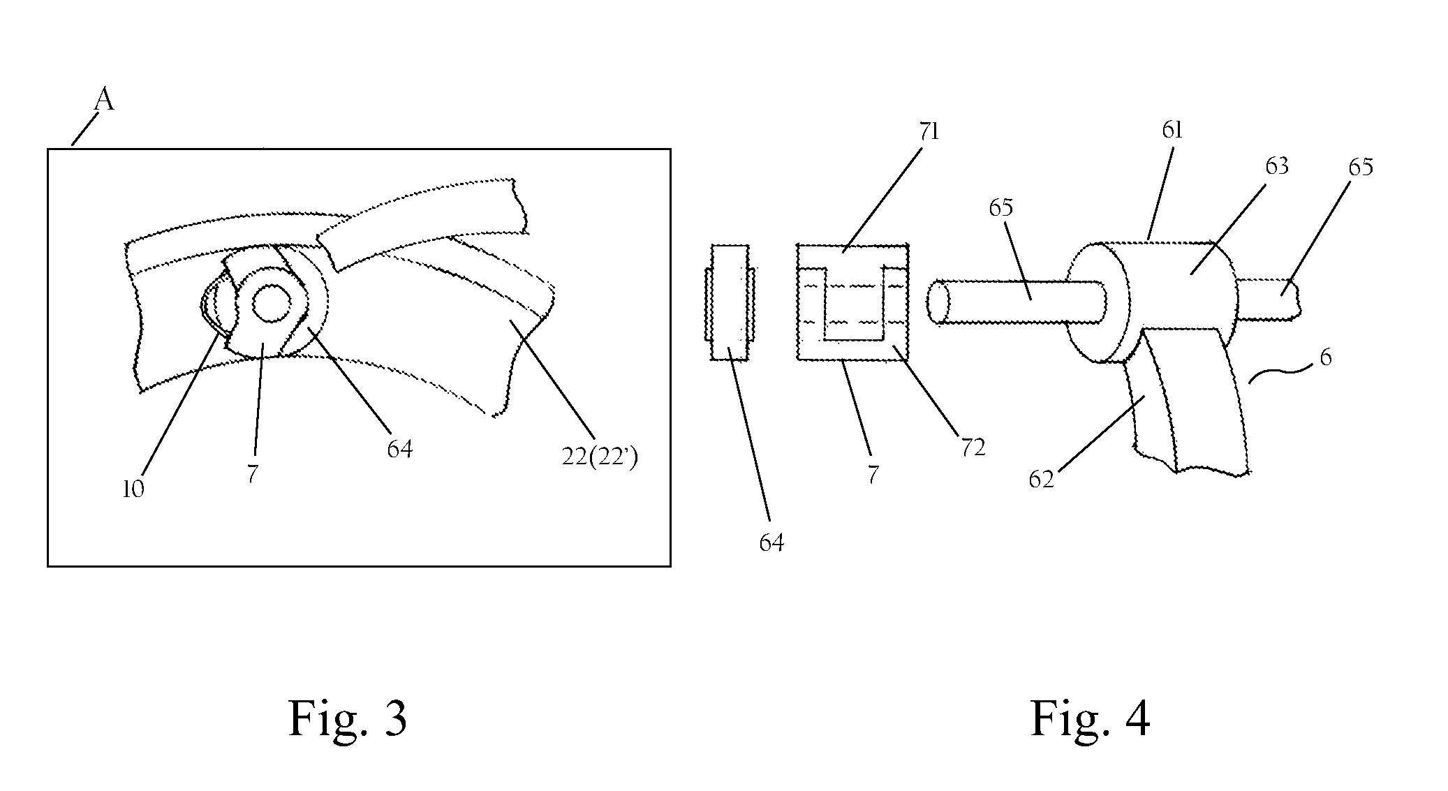
[0049]Referring to FIGS. 1-6, a continuously variable transmission of the present invention for motor vehicles or mechanical equipments is illustrated, comprising a support 1, a drive wheel 2, a toothed wheel 3, an endless sleeve 4, a ring wheel 5, a plurality of linking members 6, a plurality of wedge teeth 7, an input shaft 8, an output shaft 9 and a spring bow 10. The support 1 consists of two bearer plates 11 and a base plate 12, and the bearer plates 11 are vertically mounted at the base plate 12 in a parallel relation and have a pair of axle holes arranged at its upper and lower portions, respectively.

[0050]The drive wheel 2 is a primary wheel in round shape for power reception, in which an annular recess 22 is arranged near its periphery or outer circumferential surface. The drive wheel 2 is rotatably mounted at the axle hole of the upper portion of the bearer plate 11 by the input shaft 8. In a preferred embodiment, the drive wheel 2 consists of two relatively oblate flat wh...

third embodiment

[0073]In the third embodiment, the continuously variable transmission comprises a support 1′, a drive wheel 2′, a toothed wheel 3, an endless sleeve 4, a disk-type ring wheel 500, a plurality of rod-shaped linking members 60, a plurality of wedge teeth 7 and a spring bow 10. It should be noted that this embodiment only have the disk-type ring wheel 500 and the rod-shaped linking members 60 that are different from the above embodiments, which will be detailed hereinbelow.

[0074]Moderate modifications of the support 1′ and the drive wheel 2′ have been made in dimension, mounting and connection manners so as to be adapted for the external requirements. The other parts including the swinging roller bearing mounted between the ring wheel and the endless sleeve remain the same as in the first embodiment in terms of their structure, number and connection manner, which is omitted here and for details reference can be made to the description of the first embodiment.

[0075]As stated above, one ...


PUM


Abstract

A continuously variable transmission comprises an input shaft and an output shaft, a drive wheel, a toothed wheel or a chain wheel, an endless sleeve, a ring wheel, at least one linking member, wedge teeth or a chain, wherein the drive wheel is provided with an annular recess in which a plurality of reversal wedge teeth run, and the wedge teeth are connected with a head portion of the linking member connected with the ring wheel, the spread of axles between the drive wheel and the ring wheel is adjusted via the swinging of the endless sleeve; and with the aid of the locking and releasing operations of the wedge teeth, the linking members are urged to drive the ring wheel, whereby changing the input and output transmission ratio. The continuously variable transmission can be used in a bicycle, wherein the spread of axles between the ring wheel and the drive wheel can be adjusted by regulating a wire, and the magnitude of speed variation is not restricted, the variation range is large, and the power could be synchronously input during the speed variation.

Description

TECHNICAL FIELD[0001]The present invention relates to a transmission, and more particularly, a continuously variable transmission capable of a continuous and constant variation of a running speed thereof.BACKGROUND OF THE INVENTION[0002]In different kinds of motor vehicles, bicycles, machine equipments such as machine tools or the like, a transmission is widely used for altering input and output transmission ratios to attain a desired acceleration or deceleration.[0003]A conventional transmission basically consists of different gears of various sizes. For example, a manual or an automatic transmission for a motor vehicle may provide a 4- to 5-speed transmission, in which each speed section needs to shift in a stepped manner, namely to shift from an upper section to a lower section and then from the lower section to a next section, such an operation process would be quite complicated, and sometimes a momentary failure might occur during the shifting process.[0004]As far as a simple t...

Claims


Application Information

Patent Timeline
Patent Type & Authority Patents(United States)
IPC IPC(8): F16H29/04
CPCB62M9/085F16H29/16Y10T74/1503Y10T74/1524Y10T74/19619Y10T74/1836
Inventor KWOK, YAU CHEUNGMAK, MIU LING
Owner MAK MIU LING
Why Eureka
Try Eureka