
Coffee maker

a coffee maker and coffee technology, applied in the field of coffee makers, can solve the problems of inability to brew coffee in time, slow brewing of coffee at home, and inability to delay between the time of water addition and the brewing beginning

Inactive Publication Date: 2013-03-05
REYNOLDS D MICHAEL
View PDF42 Cites 31 Cited by
  • Summary
  • Abstract
  • Description
  • Claims
  • Application Information

AI Technical Summary

Benefits of technology

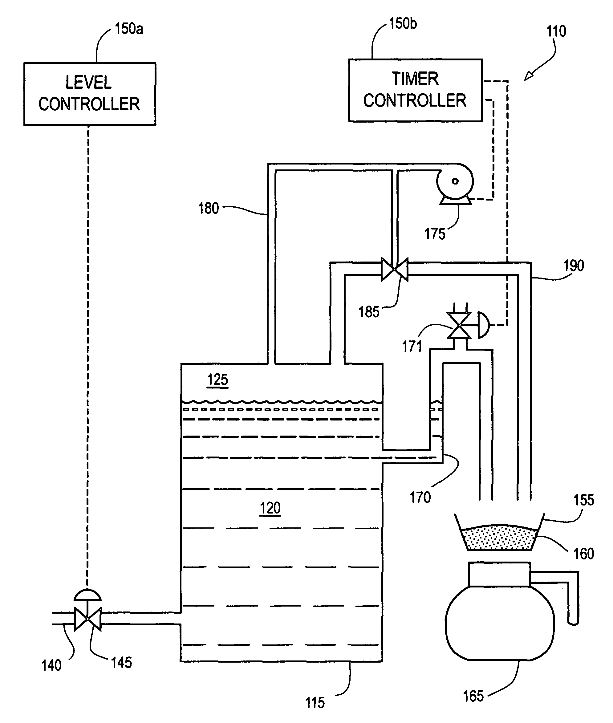
This invention is an improved coffee maker that does not require a dump valve or a continuously running air compressor. It can dispense hot water independently of when water is added and can adjust the amount of hot water needed. The coffee maker includes a heated reservoir, a siphon tube, a container for coffee grounds, and an air pump that creates pressure in the reservoir to force hot water into the siphon tube and start the flow of hot water from the reservoir to the coffee grounds container.

Problems solved by technology

Home coffee makers are relatively slow because of the time it takes for the water to heat in the reservoir.
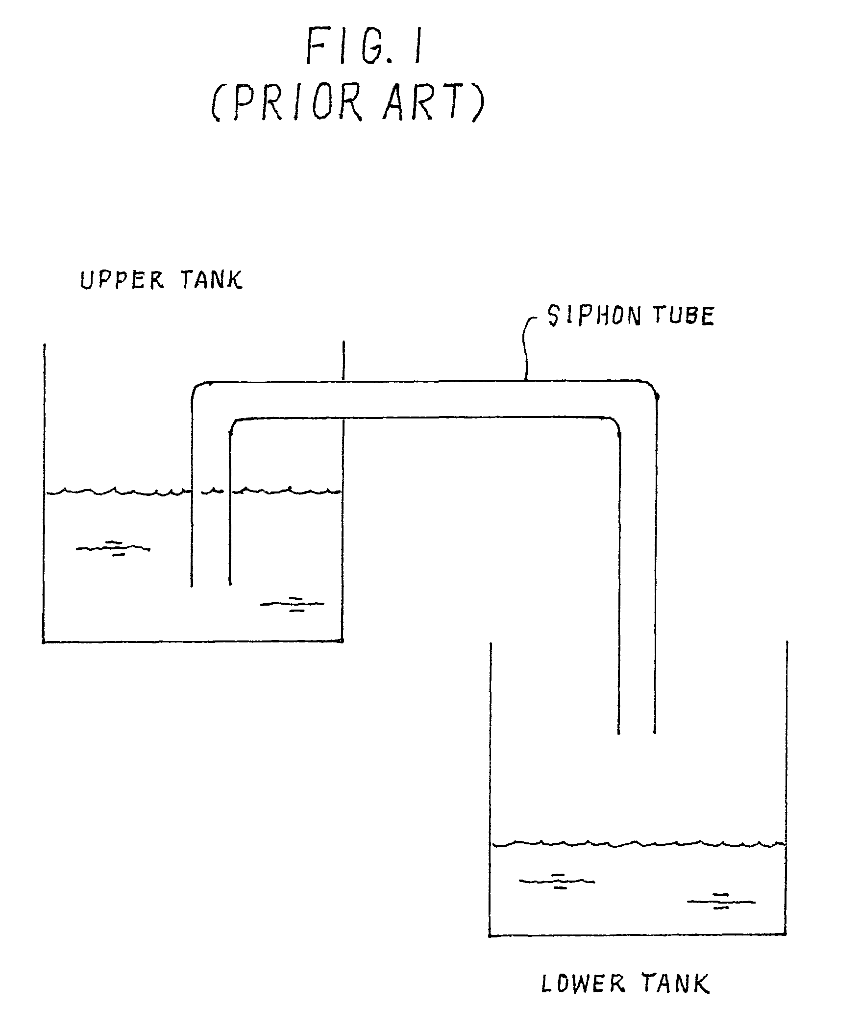
A major disadvantage of this coffee maker is that the brewing of coffee always begins at the time the water is added.
In other words, a delay between the time the water is added and the brewing begins is not possible.
Another disadvantage is that there is no means for stopping the sipon flow once it begins.
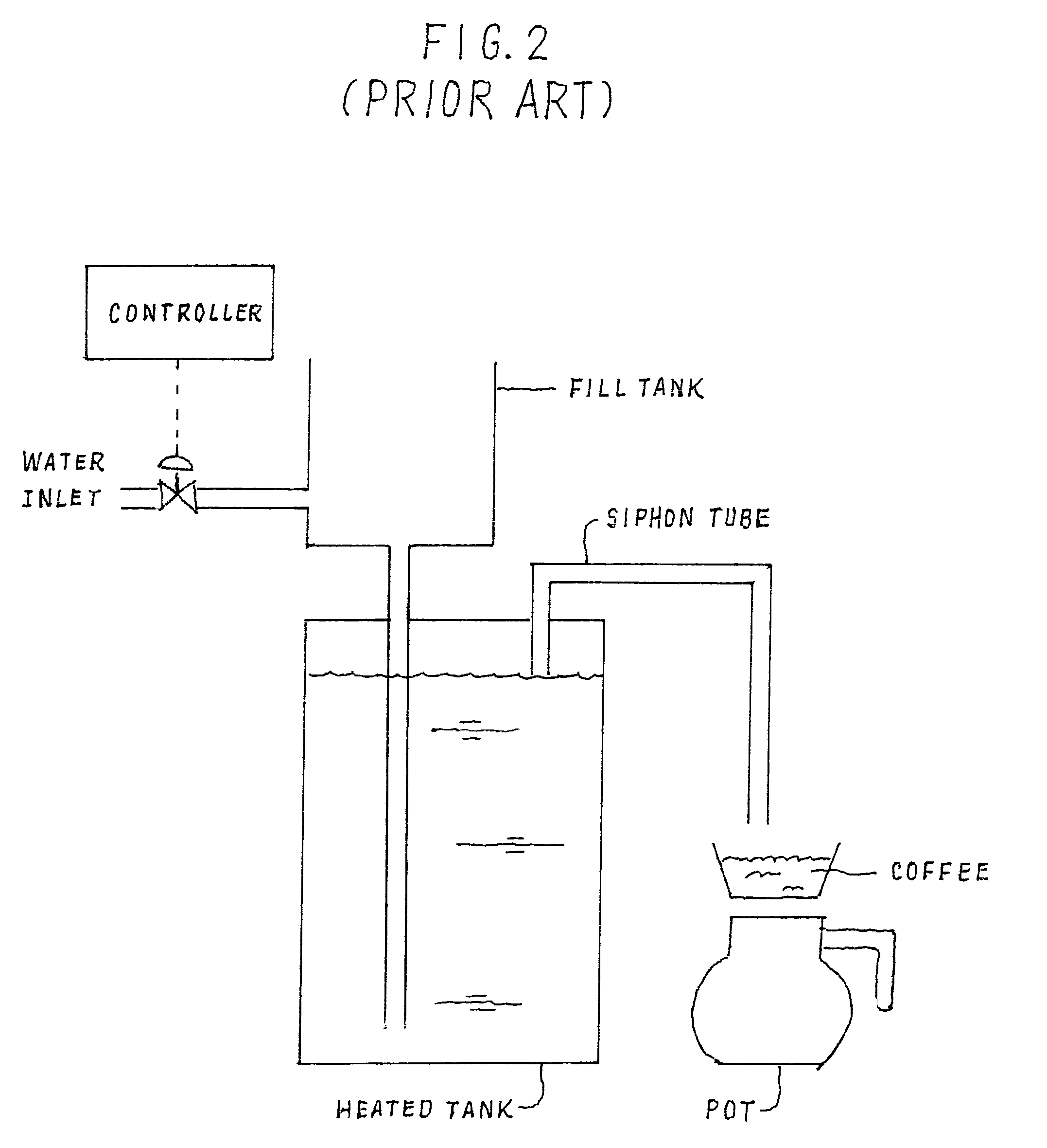
A major disadvantage of this coffee maker is that the dump valve requires frequent maintenance because lime from the hot water tends to build up at the valve.
The disadvantages of this type of coffee maker are that the air compressor is noisy and requires frequent service because it runs the entire time the coffee is being brewed.

Method used


Image

  • Coffee maker
  • Coffee maker
  • Coffee maker

Examples


first embodiment

[0023]It can be appreciated that the coffee maker does not have a dump valve that is prone to malfunction because of lime deposits. Therefore, the coffee maker of this invention never requires maintenance on a dump valve. Nor does the coffee maker have a continuously running air compressor—its air pump runs for no more than a second or two during each brewing cycle. Therefore, the coffee maker is quieter and requires little, if any, maintenance on the air pump. The coffee maker can dispense hot water independently of the time water is added. In other words, it can begin the brewing of coffee simultaneously with the addition of the cold water or it can begin the brewing at a later time because the brewing is not begun until the air pump is turned on. And finally, the coffee maker can dispense any desired volume of hot water because the volume discharged is equal to the volume added to the fill tank.

[0024]A second embodiment 110 of the coffee maker of this invention is shown in FIG. 5...

second embodiment

[0027]The operation of the coffee maker can now be considered. The level of hot water in the heated reservoir remains at the level shown in FIG. 5 at all times due to the action of the water inlet fill valve and the level controller. Both the vent valve and the stop valve are normally in the open position. When coffee is desired, the air pump is turned on for a very short period of time. The air pressure immediately closes the vent valve to seal the heated reservoir from the atmosphere and pressure quickly builds inside the heated reservoir. At the same time, the stop valve is closed. The pressure in the heated reservoir forces hot water all the way up the siphon tube. As soon as the horizontal portion of the siphon tube is filled, water begins to flow by siphon action. Pressure is no longer required so the air pump is turned off and the vent valve reopens. The time needed to initiate siphon flow is generally less than five seconds and is typically about one-half to two seconds. Onc...


PUM


Abstract

A coffee maker contains a siphon tube for discharging hot water from a heated reservoir to a container for coffee grounds. Flow through the siphon tube is initiated by pressurizing the air space in the heated reservoir with an air pump. A siphon flow of hot water through the siphon tube to a coffee grounds container then continues without pressurization. The flow is ended when the desired volume of coffee is brewed.

Description

CROSS-REFERENCE TO RELATED APPLICATION[0001]This application claims the benefit of U.S. Provisional Application Ser. No. 60 / 741,922, Dec. 2, 2005.FIELD OF THE INVENTION[0002]This invention relates to food and beverage devices. More particularly, this invention relates to coffee makers.BACKGROUND OF THE INVENTION[0003]Coffee is a drink made by passing hot water and / or steam through the roasted and ground beans of the coffee plant. The process of making coffee is commonly known as brewing. Coffee is the most popular hot drink in the United States and many foreign countries.[0004]A variety of coffee makers are used to brew coffee. Home coffee makers typically have a reservoir or tank which is usually empty. When coffee is desired, the reservoir is filled with fresh cold water, the water is heated to the desired temperature (typically about 200° F.), and then all the water is released from the reservoir to flow through the coffee grounds and into a pot. Home coffee makers are relatively...

Claims


Application Information

Patent Timeline
Patent Type & Authority Patents(United States)
IPC IPC(8): A47J31/40A47J31/02
CPCA47J31/56Y10T137/4891
Inventor REYNOLDS, D. MICHAEL
Owner REYNOLDS D MICHAEL
Learn More