
Method and system for allocation of destination calls in elevator system

a technology of elevator system and destination call, applied in the direction of elevator, transportation and packaging, etc., can solve the problems of underutilization of elevator system capacity, inability to meet the above-described call entry method, inconvenient and efficient entry of the above-described call, etc., to improve the transportation capacity of the elevator system and the traveling comfort, optimize the transportation capacity, and enhance the overall operation of the elevator system.

Active Publication Date: 2013-03-05
KONE CORP
View PDF19 Cites 24 Cited by
  • Summary
  • Abstract
  • Description
  • Claims
  • Application Information

AI Technical Summary

Benefits of technology

[0011]to improve the transport capacity of an elevator system in different traffic conditions and extraordinary situations,
[0038]Besides the above-described advantages, the present invention also provides many other advantages as compared to prior-art solutions. By applying the invention, the elevator system can be simplified by implementing some of the elevators as single-deck elevators, while at the same time the transport capacity of the elevator system in different traffic situations can be improved. The invention makes it possible to advantageously avoid the utilization of the capacity of multi-deck elevators in congested conditions to serve low-intensity traffic even if such utilization might seem to be an efficient expedient on the basis of traditional allocation methods. In the solution of the invention, passengers' special needs, such as transportation of handicapped persons, can be better attended to by using the most appropriate elevator type to serve passengers needing special transportation. The invention further provides the possibility that, when the multi-deck elevators used in the elevator system are double-deck elevators, calls can be allocated on the so-called odd / even principle, thereby maximizing the transport capacity of the double-deck elevators. Furthermore, the multi-deck elevators need not necessarily be provided with any specific adjustment means for the adjustment of inter-car distances because, in the solution of the invention, floors spaced at irregular intervals can be advantageously served using single-deck elevators.

Problems solved by technology

However, the above-described call entry method is impractical and inefficient in tall buildings, which is why call entry in the elevator systems in such buildings is increasingly implemented using a so-called destination call system, wherein each passenger gives his / her individual destination data already at the starting floor, e.g. in the elevator lobby before boarding an elevator car.
In this case, the group control has no chance to subsequently change the elevator serving the call and is therefore unable to optimize the selected elevator routes, whereas such possibilities are available in elevator systems using the traditional up / down call entry method.
Allocation performed immediately on the basis of a call may thus be unfavorable when new calls are to be allocated after a previously entered call, leading to underutilization of the capacity of the elevator system.
The multi-deck elevator is ill adapted for certain special applications, such as e.g. for use as a fire-fighting elevator, because in this application it may be required that, to provide the service capacity prescribed by elevator regulations, extra floor space be provided at the upper or lower end of the elevator shaft.
Besides, multi-deck elevators are more complex in respect of both mechanical construction and control system as compared to single-deck elevators.
The structural complexity of multi-deck elevators may also be increased as a result of variation in the floor heights of the building, because in such cases the multi-deck elevator has to be provided with a mechanism that allows the mutual distance between the elevator decks to be varied according to the floor height so as to permit simultaneous service to the floors in question.
On the whole, the use of multi-deck elevators increases the acquisition and maintenance costs of elevator systems, and therefore multi-deck elevator systems are expensive.

Method used


Image

  • Method and system for allocation of destination calls in elevator system
  • Method and system for allocation of destination calls in elevator system
  • Method and system for allocation of destination calls in elevator system

Examples


Embodiment Construction

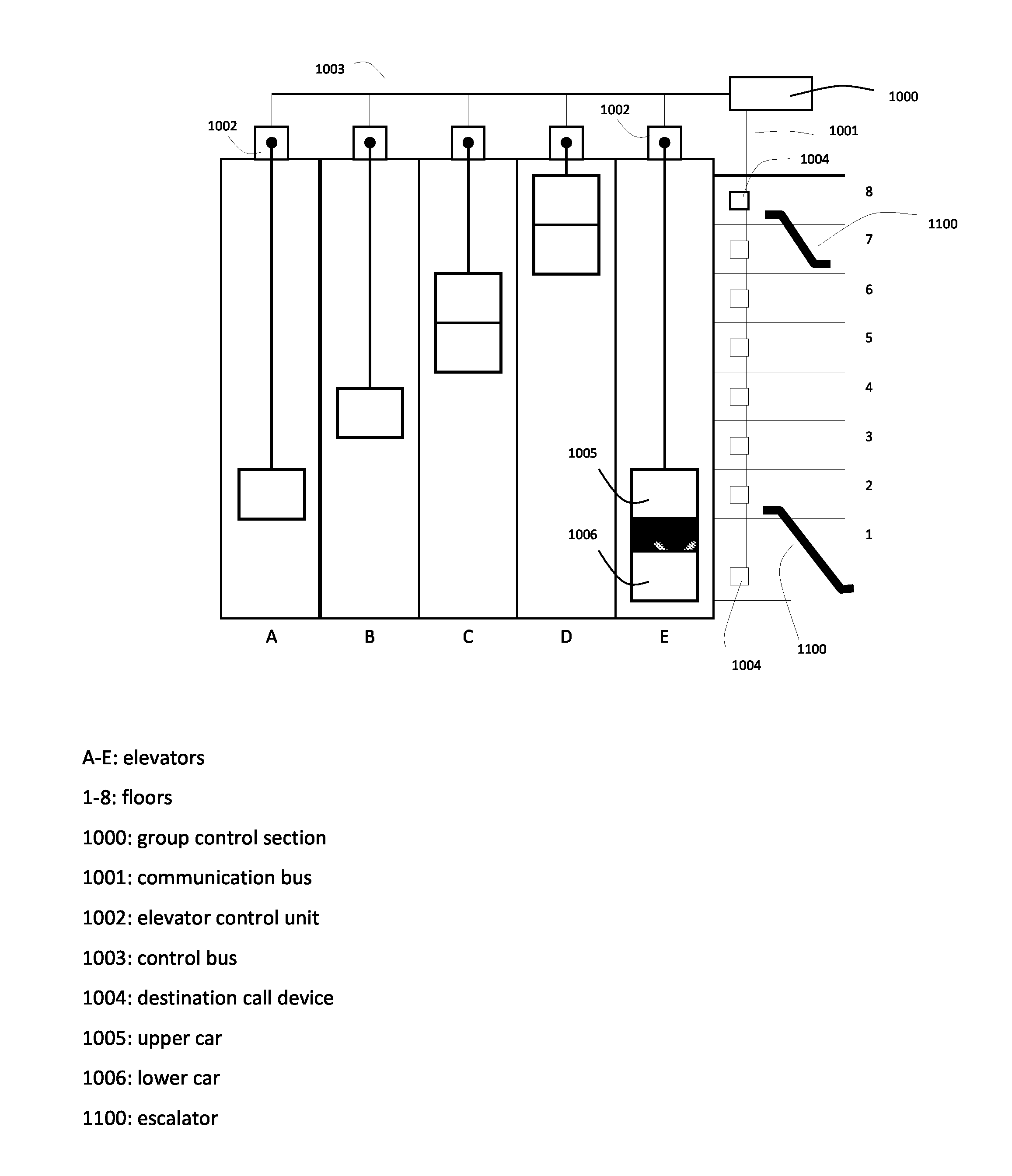
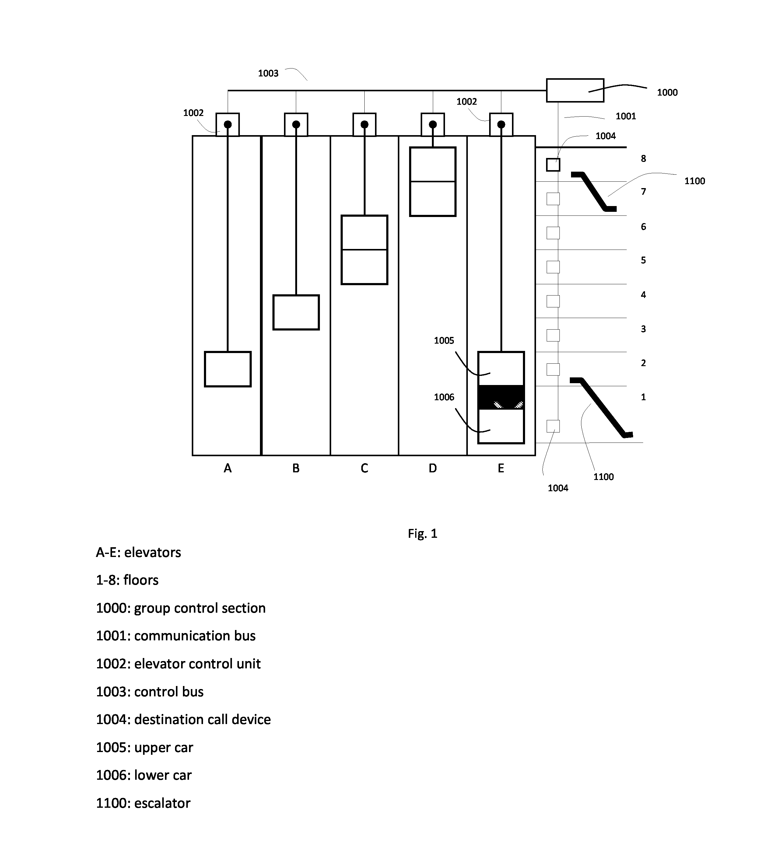
[0042]FIG. 1 presents an elevator system in which the solution of the invention is applied. The elevator system comprises five elevators A . . . E. Of these, elevators A and B are single-deck elevators while elevators C, D and E are double-deck elevators. In the building, the elevators serve floors 1-8, floor 1 being the entrance / exit lobby of the building and floor 8 the upper lobby of the building. Provided between floors 1 and 2 and between floors 7 and 8 are escalators 1100, which the passenger can use for easy passage from one floor (waiting lobby) to another e.g. when calls are allocated to the double-deck elevators C, D, E, thus ensuring more effective utilization of especially the double-deck elevators. From FIG. 1 it can also be seen that floor 1 has a larger floor height that the other floors, and thus the upper car 1005 and lower car 1006 of the elevator E at floors 1 and 2 have been adjusted to an inter-car distance larger than the inter-car distance of the double-deck e...


PUM


Abstract

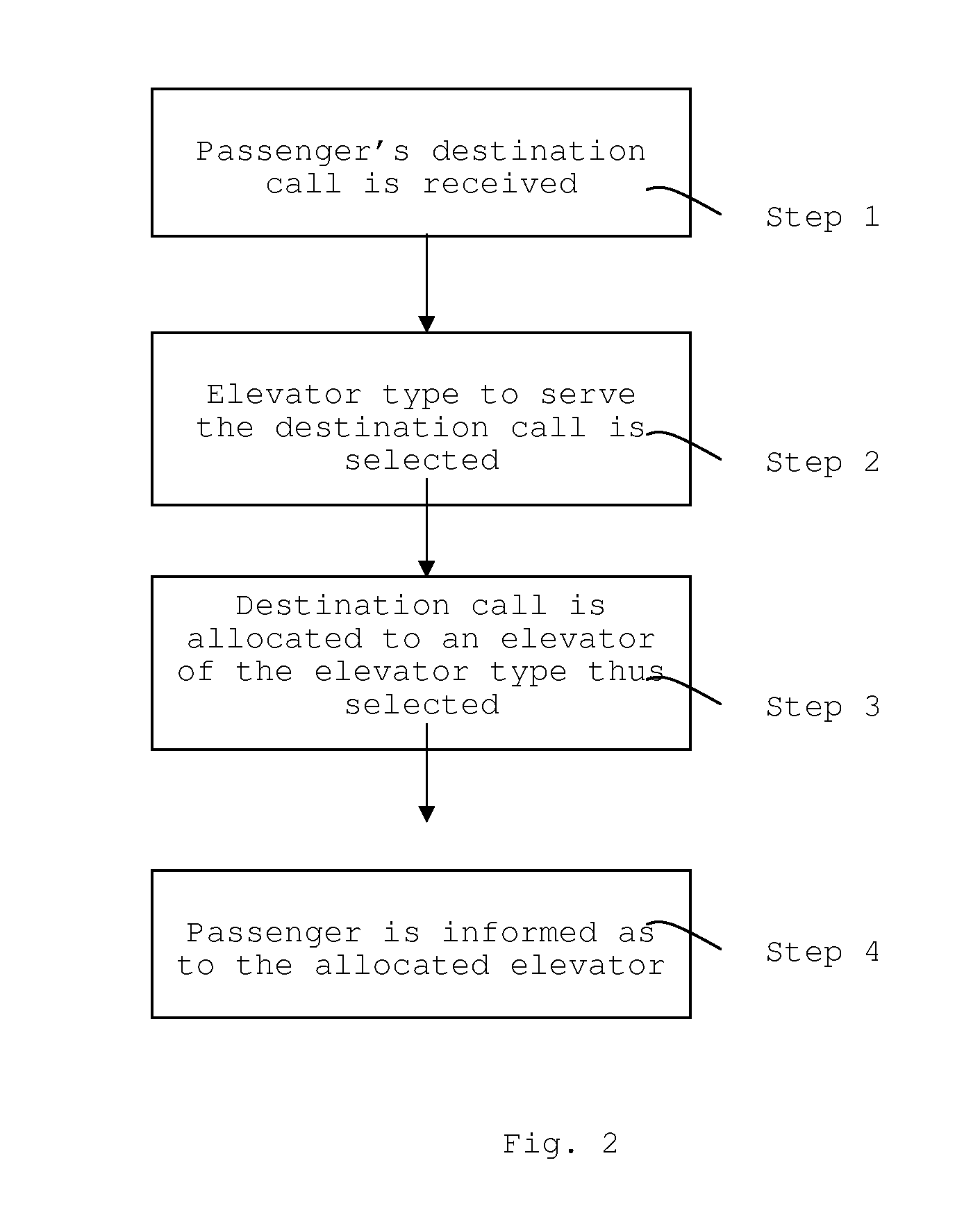
A solution for the allocation of destination calls in an elevator system includes one or more single-deck elevators and one or more multi-deck elevators, in which system the passenger enters a destination call via a destination call device. The destination call entered by the passenger is received, an elevator type to serve the destination call is selected on the basis of an elevator type selection criterion, and the destination call is allocated to an elevator consistent with the elevator type thus selected.

Description

[0001]This application is a Continuation of PCT International Application No. PCT / FI2008 / 000101 filed on Sep. 12, 2008, which claims the benefit to Patent Application No. 20070766 filed in Finland, on Oct. 11, 2007. The entire contents of all of the above applications is hereby incorporated by reference.BACKGROUND OF THE INVENTION[0002]1. Field of the Invention[0003]The present invention relates to elevator systems. In particular, the invention relates to a method and system for allocating destination calls in an elevator system comprising both single-deck and multi-deck elevators.[0004]2. Background of the Invention[0005]Tall buildings typically contain numerous elevators, escalators and other corresponding conveying means for transporting people from one floor to another in the building. When a passenger inputs a call for an elevator, the group control function of the elevator system allocates an elevator to serve the passenger according to the situation prevailing in the elevator...

Claims


Application Information

Patent Timeline
Patent Type & Authority Patents(United States)
IPC IPC(8): B66B1/18
CPCB66B1/2458B66B2201/103B66B2201/211B66B2201/212B66B2201/405B66B2201/216B66B2201/222B66B2201/306B66B2201/402B66B2201/215B66B1/20
Inventor LAIHANEN, PENTTITURPEINEN, JUKKADE JONG, JOHANNES
Owner KONE CORP
Learn More