Arrangement for supporting load in transportation unit

a technology for supporting load and transportation unit, which is applied in the direction of loading/unloading vehicle arrangment, transportation items, load accommodation, etc., can solve the problems of large impact load on inability to support and tighten the load, and the support arrangement does not enable the position and lock of the rod-like support member against the load, so as to achieve easy and quick arrangement, load may be heavy

Active Publication Date: 2013-03-05
OY LANGH SHIP AB
View PDF17 Cites 7 Cited by
  • Summary
  • Abstract
  • Description
  • Claims
  • Application Information

AI Technical Summary

Benefits of technology

[0005]It is an object of the invention to provide a new support arrangement that eliminates the above-mentioned prior-art problems and permits safe support for high and narrow loads when the loads are transported in different transportation units, such as different vehicles and transportation means.
[0008]the support arrangement comprises an elongated flexible member and a tightening means for tightening the elongated flexible member against the load to be supported so that displacement of the load in relation to the rod-like member is prevented.
[0010]the first support end of the rod-like support member is adapted to be fastened to the first support point in the first rail and the second support end of the rod-like support member is adapted to be fastened to the second support point in the second rail for positioning the rod-like support member in a locked position in which its free movement in the longitudinal direction of the transportation unit is prevented,
[0013]the elongated flexible support member is arranged to turn the rod-like support member and its support ends so that the gripping edges of the rod-like support member wedge by biting into the inner walls of the grooves of the rails to bring the rod-like support member into its locked position the rod-like support member comprising power transmission brackets in cooperation with the elongated flexible member, which are arranged to transmit a torque to the rod-like support member for turning it, when the elongated flexible member is tightened with tightening means connected thereto and arranged to uphold a torque exerted on the rod-like support member and keep the rod-like support member in its locked position so that its free movement relative to the transportation unit is prevented. Such an embodiment keeps the load in place in the transportation unit and prevents the load from being displaced relative to the longitudinal axis of the transportation unit.
[0014]A great advantage of the support arrangement of the invention is that it makes it possible to securely support different loads, even a high and narrow load, in different types of transportation units so that the load cannot during transportation move in the transportation unit. When the elongated flexible member is also arranged around the load to be supported, the load to be supported can be pressed between the support member and elongated flexible member when the elongated flexible member is tightened with the tightening means. If, in the embodiment of the invention comprising a rod-like support member whose support ends comprise diametrical gripping edges, the load strives at moving during transportation, the load causes to the elongated flexible member of the support arrangement a force that endeavors to turn the rod-like support member and makes the gripping edges of the rod-like support member to lock even tighter to the support points in the transportation unit, that is, to the longitudinal inner walls of the grooves of the rails, which inner walls receive the gripping edges. Thus, the support arrangement is self-tightening, which is a great advantage when compared to known support arrangements. The support arrangement also provides the advantage that it is easy and quick to arrange around the load to be transported to support it. Thanks to being self-tightening the gripping edges are caused to grip even to smooth inner walls. Because the elongated flexible member and the tightening means flex elastically, the gripping force of the gripping edges to the inner walls prevails even if slight changes occurred in the outer dimensions of the supported load during transportation. The outer dimensions of the load may slightly change due to the fact, for example, that the packaging material of the load compresses slightly when stresses are directed to it during transportation. Thus, the elongated flexible member and the tightening means attached thereto ensure that the support rod and load to be supported remain stationary in all situations. Because the support provided by the support arrangement is extremely secure, the load may be heavy; an example of which is large-diameter narrow metal reels.

Problems solved by technology

A problem with the support arrangement is that it cannot support and tighten the load to be supported in such a way to avoid harmful displacements of the load to be supported, if the transportation unit moves back and forth during transportation.
Harmful displacements include here typically such displacements or movements which cause the load to overturn and which bring about large impact loads on the rod-like support member.
The support arrangement does not enable to position and lock the rod-like support member against the load, on both sides of the load in such a way that the load would be supported substantially without clearance by both support member simultaneously.
Even a small gap or clearance between the support members and the load causes great loads on both the support members and the load if the load moves back and forth for instance during sea transport in rough seas.
Such a gap will inevitably always develop in this known support arrangement if the load comprises a casing which will be pressed and shrink somewhat owing to external forces.
The transportation and supporting of a high, narrow and heavy load with known support arrangements has proven to be especially problematic.
Their transport and supporting has proven difficult especially in lorries, but also in trains, ships and airplanes, in which the reels are typically transported in containers.

Method used


Image

  • Arrangement for supporting load in transportation unit
  • Arrangement for supporting load in transportation unit
  • Arrangement for supporting load in transportation unit

Examples


Embodiment Construction

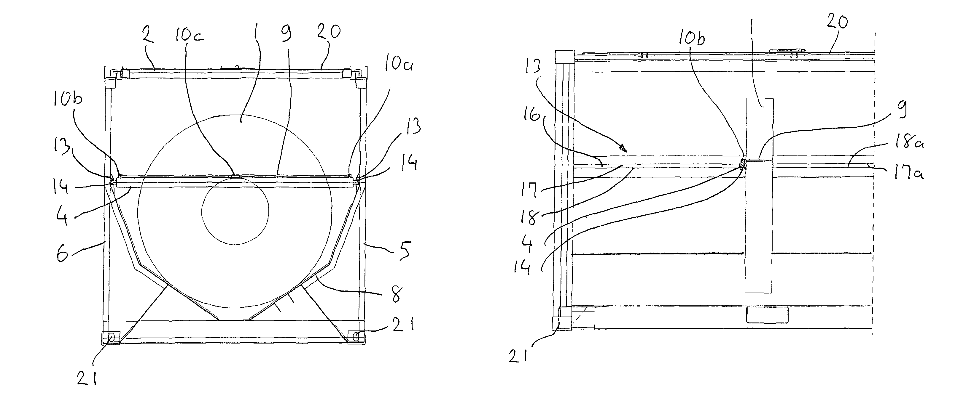
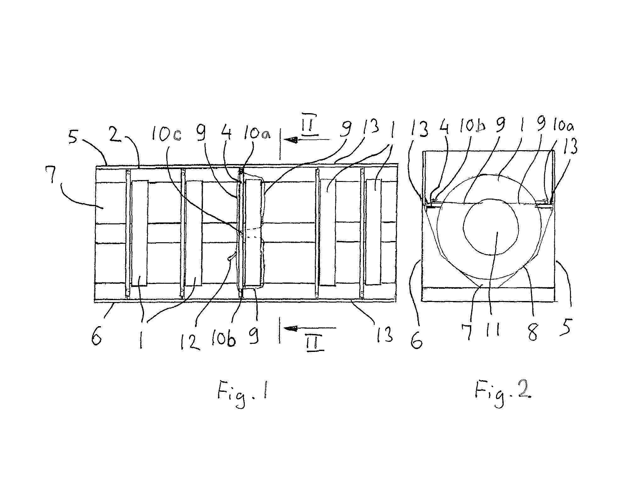
[0031]FIG. 1 is a top view of a container 2, in which five metal reels 1 have been loaded. The container 2 is not loaded full of reels, because its strength would not be sufficient to carry a large number of reels. The diameter of the reels 1 is approximately 190 cm and their width is approximately 30 cm. As shown in the figure, the reels are arranged at a distance from each other, whereby they load the container evenly.

[0032]FIG. 2 shows a section along line II-II of FIG. 1. FIGS. 1 and 2 show that the reels 1 are arranged in a chute 7 that extends from one end of the container to the other. The chute 7 comprises oblique support surfaces 8, to which the mantle surface of the reel 1 is supported.

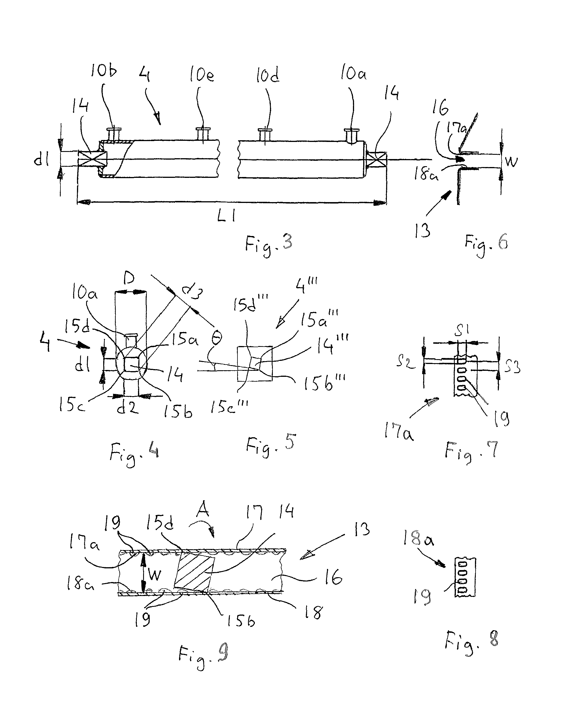
[0033]Each reel 1 is supported with a support arrangement that comprises a support rod 4 and rope 9. The support rod 4 supports the reel 1 on one side and the rope 9 is wound around the reel 1 such that it supports the reel on the opposite side. The rope 9 is fastened to a first bracket 10a ...


PUM


Abstract

A support arrangement for supporting load in a transportation unit, includes a rod-like support member placed beside the load to support it and two parallel rails in the longitudinal direction of the transportation unit and at a distance from each other. The support member includes support ends for fastening to support points in the transportation unit so that the support member is perpendicular to the longitudinal axis of the transportation unit. Safe and easily implemented support for the load to be transported is achieved by arranging the support member to move along the inner walls of the rails and guided by the inner walls to set it against the load. The support arrangement includes an elongated flexible member and a tightening element for tightening the elongated flexible member against the load so that displacement of the load in relation to the rod-like member is prevented.

Description

RELATED APPLICATION[0001]This is a continuation-in-part (CIP) of International PCT Application PCT / FI2010 / 050112, filed on Feb. 19, 2010, which claims priority to Finnish Application No. 20095156 filed on Feb. 19, 2009. The entire contents of each of the above-identified applications are hereby incorporated by reference.BACKGROUND OF THE INVENTION[0002]The invention relate to a support arrangement for supporting load in a transportation unit, such as container or vehicle for transporting load, the support arrangement comprising a rod-like support member and a first and a second rail which forms longitudinal grooves and support points arranged in the longitudinal direction of the rails for receiving the support member at a given support point beside the load to support it, the rod-like support member comprising a first support end for positioning to a first support point in the first rail and a second support end opposite to the first support end for positioning to a second support p...

Claims


Application Information

Patent Timeline
Patent Type & Authority Patents(United States)
IPC IPC(8): B60P7/08
CPCB60P7/15B61D45/001B65D85/64B60P7/0815B61D45/003B65D85/66B65D90/004
Inventor LANGH, HANS
Owner OY LANGH SHIP AB
Why Eureka
Try Eureka